
Sheet material punching structure for buildings and bridges

A technology for bridges and hole structures, applied in the directions of cleaning methods and appliances, boring/drilling, maintenance and safety accessories, etc. Easy to operate and avoid clogging

Inactive Publication Date: 2020-08-21
顾轩波
View PDF0 Cites 3 Cited by
  • Summary
  • Abstract
  • Description
  • Claims
  • Application Information

AI Technical Summary

Problems solved by technology

[0004] The purpose of the present invention is to solve the shortcomings of the existing punching device, which has a single function, needs to manually move the board, cannot automatically fix the board, and cannot collect debris, and proposes a board punching device for buildings and bridges. Pore ​​structure

Method used


Image

  • Sheet material punching structure for buildings and bridges
  • Sheet material punching structure for buildings and bridges
  • Sheet material punching structure for buildings and bridges

Examples


Embodiment 1

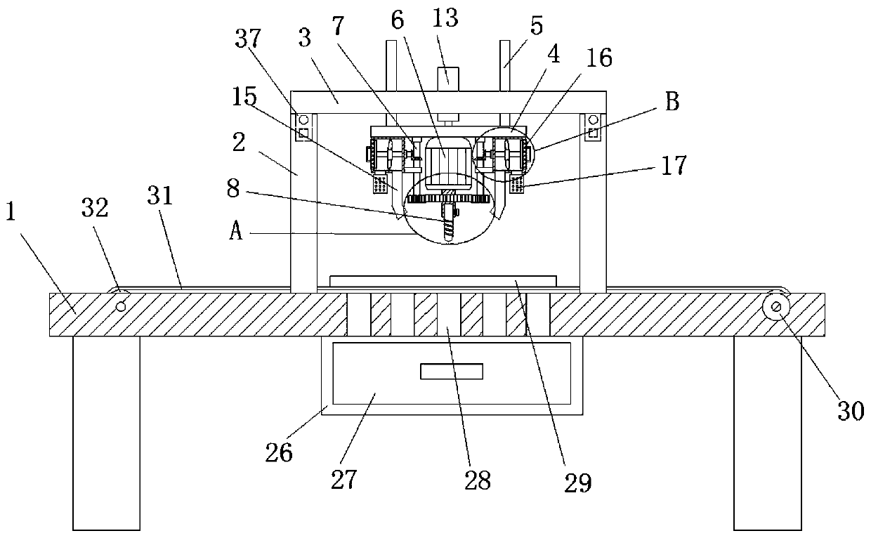
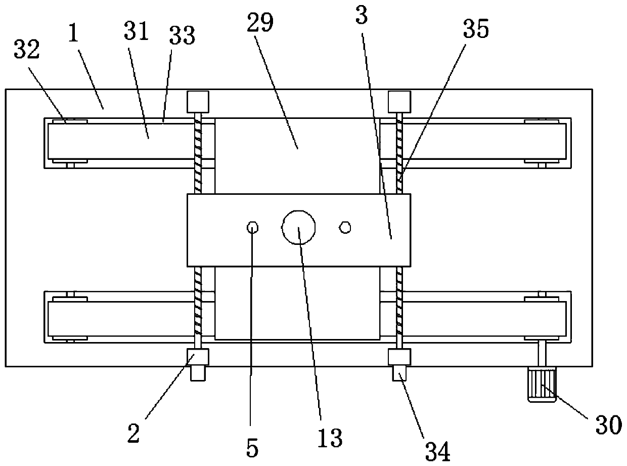
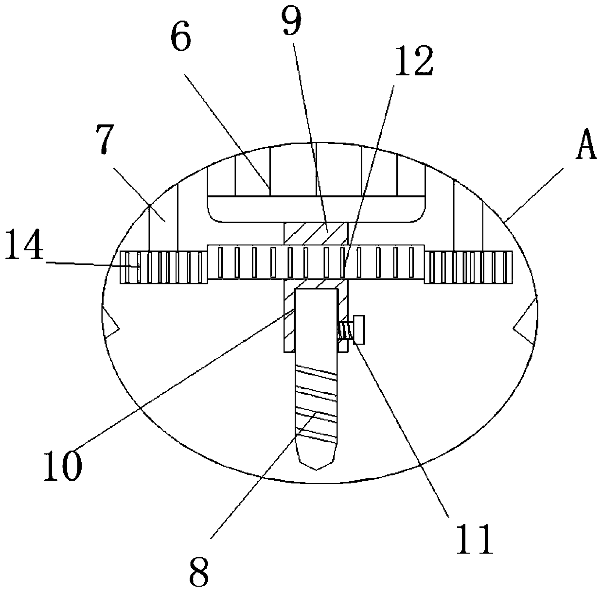
[0032] refer to Figure 1-6 , a plate punching structure for buildings and bridges, comprising a work plate 1, a transmission mechanism is arranged on the top of the work plate 1, a plate 29 is placed on the transmission mechanism, and the top of the work plate 1 is fixedly connected with four poles 2, four Each pole 2 is movably connected with the same top plate 3, and the two poles 2 located on the same horizontal line are connected with a driving mechanism. The top plate 3 is compatible with the two driving mechanisms. There is a propulsion motor 13, the output shaft of the propulsion motor 13 is fixedly connected with a lifting plate 4, the bottom of the lifting plate 4 is fixedly connected with a motor 6, the output shaft of the motor 6 is fixedly connected with a round shaft 9, and the bottom of the round shaft 9 is movably connected There are drill bits 8, two vertical shafts 7 are installed symmetrically on the bottom of the lifting plate 4, and the two vertical shafts...


PUM


Abstract

The invention belongs to the technical field of sheet material punching, particularly relates to a sheet material punching structure for buildings and bridges. Aiming at solving the problems that an existing punching device is single in function, sheet materials need to be manually moved, the sheet materials cannot be automatically fixed, and chippings cannot be collected, the following scheme isprovided. According to the scheme, the device comprises a working plate, a conveying mechanism is arranged at the top of the working plate, the sheet materials are placed on the conveying mechanism, four supporting rods are fixedly connected to the top of the working plate, the four supporting rods are movably connected with the same top plate, the supporting rods located on the same horizontal transverse lines are connected with driving mechanisms, the top plate is matched with the two driving mechanisms, a propelling motor is embedded in the working plate, a lifting plate is fixedly connected to an output shaft of the propelling motor, and a motor is fixedly connected to the bottom of the lifting plate. According to the device, the operation is convenient, the sheet materials can be automatically moved, the sheet materials can be automatically fixed, and the chippings can be collected.

Description

technical field [0001] The invention relates to the technical field of plate punching, in particular to a plate punching structure for buildings and bridges. Background technique [0002] The sheet material is a flat rectangular building material board made into a standard size. The sheet material is used in construction and bridge construction, and the sheet material used in construction and bridge construction requires memory punching. [0003] The existing punching device has a single function and needs to manually move the plate, but cannot automatically fix the plate and cannot collect debris. Contents of the invention [0004] The purpose of the present invention is to solve the shortcomings of the existing punching device, which has a single function, needs to manually move the board, cannot automatically fix the board, and cannot collect debris, and proposes a board punching device for buildings and bridges. hole structure. [0005] In order to achieve the above ...

Claims


Application Information

Patent Timeline
Patent Type & Authority Applications(China)
IPC IPC(8): B23B47/00B23B39/14B23Q3/06B23Q11/00B23Q11/08B08B1/00B08B1/04
CPCB23B47/00B23B39/14B23Q11/0046B23Q11/0067B23Q11/08B23Q3/06B08B1/10B08B1/32
Inventor 顾轩波
Owner 顾轩波
Learn More