A glass plate beveling device

A glass plate and mounting plate technology, applied in the field of glass plate chamfering devices, can solve the problems of easy manual damage, time-consuming and labor-intensive, etc., and achieve the effects of improving efficiency, reducing manual operation, and facilitating manual replacement of glass plates.

Active Publication Date: 2022-01-07
宜兴市于氏特种玻璃有限公司
View PDF9 Cites 0 Cited by
  • Summary
  • Abstract
  • Description
  • Claims
  • Application Information

AI Technical Summary

Problems solved by technology

[0004] In order to overcome the shortcomings of manually beating the glass plate for chamfering, which requires multiple manual operations, laborious and labor-intensive, and easy to be damaged manually, the technical problem to be solved is to provide a glass that automatically chamfers the glass plate, slows down manual operations, and improves operational safety. Board chamfering device

Method used


Image

  • A glass plate beveling device
  • A glass plate beveling device
  • A glass plate beveling device

Examples


Embodiment 1

[0055] A glass plate chamfering device, such as figure 1 As shown, it includes a base 1, a support rod 2, a support platform 3, a support frame 4, a motor 5, a beating mechanism 6, an intermittent rotation mechanism 7, a pressing mechanism 8 and a fixed block 11. There are support rods 2, a support platform 3 is provided between the tops of the two support rods 2, a motor 5 is installed on the right side of the base 1, and the motor 5 is located on the right side of the support rod 2, and a beating mechanism 6 is provided on the top of the support platform 3, and the beating mechanism 6 Connected with the motor 5, the left side of the base 1 is equipped with an intermittent rotation mechanism 7, the intermittent rotation mechanism 7 is connected with the beating mechanism 6, the left side of the base 1 is provided with a support frame 4, and the intermittent rotation mechanism 7 is located between the support frame 4 and the support rod 2 , A pressing mechanism 8 is installed ...

Embodiment 2

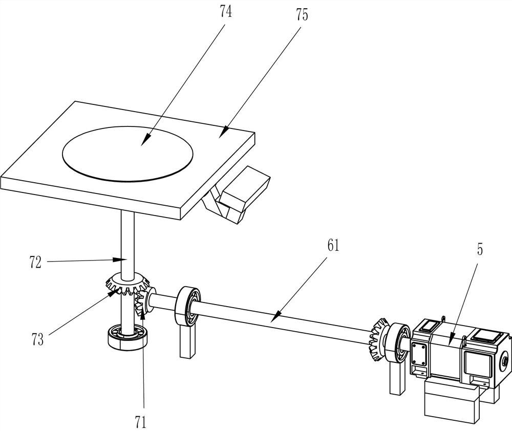
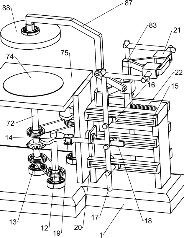
[0058] Specifically, such as Figure 1-3 and Figure 5 As shown, the knocking mechanism 6 includes a first rotating shaft 61, a first bevel gear 62, a cylindrical block 63, a guide block 65, a slide bar 66, a hammer 67, a first spring 68, a second rotating shaft 69 and a second bevel gear 610, the right side of the base 1 is rotatably provided with a first rotating shaft 61, the right end of the first rotating shaft 61 is connected with the output shaft of the motor 5, the first bevel gear 62 is installed on the right side of the first rotating shaft 61, and the top of the supporting platform 3 rotates The formula is provided with a cylindrical block 63, and the side of the cylindrical block 63 is provided with a chute 64, and three-quarters of the chute 64 is wave-shaped, and one-quarter of the chute 64 is arranged in parallel, supporting A guide block 65 is installed on the left side of the top of the table 3, and the inside of the guide block 65 is slidably provided with a...

Embodiment 3

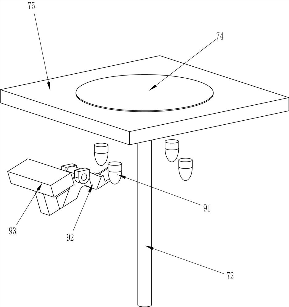
[0065] according to figure 1 , Figure 3-4 and Figure 6-7 As can be seen from the diagram, it also includes a pusher mechanism 9, which includes a bump 91, an L-shaped connecting rod 92 and a push block 93, and bumps 91 are installed on the front, rear, left, and right sides of the bottom of the turntable 74, and the workbench 75 right The bottom of the side is rotatably equipped with an L-shaped connecting rod 92, which cooperates with the protrusion 91, and the end of the L-shaped connecting rod 92 is connected with a push block 93.

[0066] When the hammer 67 knocks the corner of the glass plate away and the turntable 74 starts to rotate, the turntable 74 rotates to drive the bump 91 to contact the L-shaped connecting rod 92, the L-shaped connecting rod 92 swings counterclockwise, and the push block 93 swings upwards, thereby jacking up At the bottom of the corner of the glass plate knocked off, when the bump 91 is out of contact with the L-shaped connecting rod 92, the ...


PUM


Abstract

The invention relates to a chamfering device, in particular to a chamfering device for a glass plate. The technical problem to be solved: provide a glass plate chamfering device that automatically chamfers the glass plate, slows down the manual operation, and improves the operation safety. The technical solution is: a glass plate chamfering device, including: a base, two support rods are symmetrically installed in the middle of the side, and the support table is arranged between the tops of the two support rods; a motor, a base near the side of the support rod A motor is installed on the side, and the beating mechanism is arranged on the top of the supporting platform. The invention realizes the automatic beating of the glass plate through the beating mechanism without manual repeated beating, which improves the efficiency of chamfering of the glass plate, and the purpose of automatic rotation of the glass plate can be achieved through the intermittent rotating mechanism, and the quarter-tooth conical The gear is designed to ensure that the glass plate only turns ninety degrees at a time so that the corners of the glass plate are automatically positioned under the hammer.

Description

technical field [0001] The invention relates to a chamfering device, in particular to a chamfering device for a glass plate. Background technique [0002] At present, when removing the four corners of a square glass plate, workers usually stack multiple glass plates together, hold the glass plate with one hand, and repeatedly tap the corners of the glass plate with a small hammer in the other hand. Then fall down into the waste box, then turn the glass plate, tap the corner of the next glass plate with a small hammer, and repeat this many times, all the corners of the glass plate can be removed, but this method of removing glass by manual knocking The way of the corner of the plate needs to manually rotate the glass plate many times, the efficiency of the corner removal of the glass plate is low, and the sharp glass plate is very easy to scratch the human body. [0003] The above method of manual beating to remove the corners of the glass requires multiple manual operations...

Claims


Application Information

Patent Timeline
Patent Type & Authority Patents(China)
IPC IPC(8): B28D1/28B28D7/04
CPCB28D1/28B28D7/04
Inventor 刘庆豪
Owner 宜兴市于氏特种玻璃有限公司
Why Eureka
Try Eureka