End-in and side-out pusher type heating furnace automatic positioning tapping device

An automatic positioning and steel-pushing technology, which is applied to heat treatment furnaces, lighting and heating equipment, furnaces, etc., to avoid manual high-intensity work and realize the effect of automation

Active Publication Date: 2017-10-13
HUATIAN NANJING ENG & TECH CORP MCC
View PDF4 Cites 0 Cited by
  • Summary
  • Abstract
  • Description
  • Claims
  • Application Information

AI Technical Summary

Problems solved by technology

[0004] In view of the problem that the current end-in and side-out push steel heating furnace relies on manual judgment of the position of the steel billet and requires manual control equipment, the present invention provides an end-in and side-out furnace that automatically detects and accurately locates the position of the steel billet and automatically controls the operation of the equipment through signals. Pusher type heating furnace automatic tapping positioning device

Method used


Image

  • End-in and side-out pusher type heating furnace automatic positioning tapping device
  • End-in and side-out pusher type heating furnace automatic positioning tapping device
  • End-in and side-out pusher type heating furnace automatic positioning tapping device

Examples


Embodiment 1

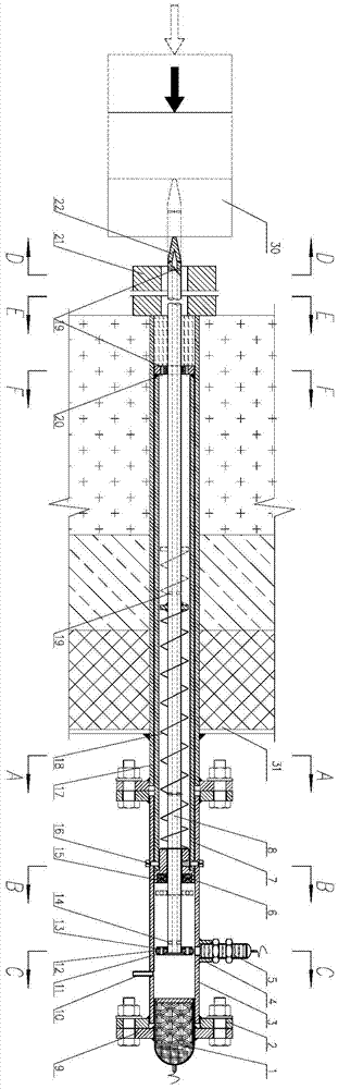
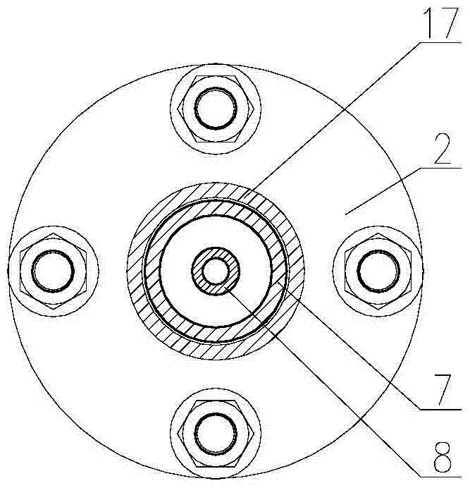
[0024] As shown in the figure, the end-in and side-out pushing type heating furnace automatic tapping positioning device in this embodiment includes a casing and a probe guide rod 8 arranged in the casing. The inside of the right end of the casing is fixed with an electromagnet 1 through a flange 2 and a special-shaped flange 9, and is spaced at a certain distance from the electromagnet 1, and an inductive sensor 5 is fixed on the left side of the casing wall of the electromagnet 1, The inductive sensor 5 is fixed on the top of the casing wall by the threaded sleeve 4 that is sleeved on its outside, and a permanent magnet 6 is arranged at a certain distance on the left side of the inductive sensor 5, and the middle part of the permanent magnet 6 A gap is left, and the probe guide rod 8 passes through the gap in the middle of the permanent magnet 6 .

[0025] A plurality of support seats are provided at the inner distance of the casing, and the probe guide rod 8 is arranged on ...

Embodiment 2

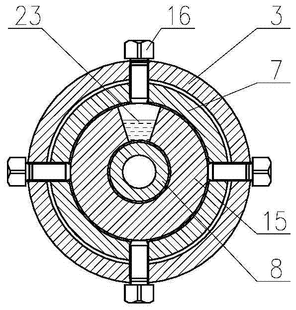
[0037] In this embodiment, the end-in and side-out pusher type heating furnace automatic tapping positioning device is based on Embodiment 1, and discloses a specific structure of a bushing. The bushing includes interconnected first sub-sleeves 7 , the second sub-sleeve 3, the nozzle diameter of the first sub-sleeve 7 is slightly smaller than the nozzle diameter of the second sub-sleeve 3, and one end of the second sub-sleeve 3 is sleeved on the first sub-sleeve On one end of the pipe 7, the two are connected by threads, and are fixed and locked by bolts, thereby fixing the two sleeve pipes together. The length selection of the first sub-sleeve 7 and the second sub-sleeve 3 is preferably when the whole device is installed on the furnace wall, and the installation and connection positions of the two sub-sleeves are located outside the furnace wall.

[0038] In this embodiment, the casing structure of the automatic tapping positioning device for the end-in and side-out pushing t...

Embodiment 3

[0040] In this embodiment, the end-in and side-out pushing type heating furnace automatic tapping positioning device is based on Embodiment 1 or Embodiment 2, and the compressed air pipe is connected to the casing on the right side of the casing, that is, on the outside of the furnace wall. 10. The probe guide rod is preferably a hollow structure, and an air inlet 14 is provided on the probe guide rod, and corresponding air diffuser holes 19 are provided; a communication sleeve is provided on the displacement signal plate 12 of the probe guide rod. Air guide holes 13 inside the tube.

[0041] In this embodiment, the end-in and side-out pusher type heating furnace automatic tapping positioning device allows compressed air to enter the bushing through the compressed air pipe 10, and further compressed air enters the probe guide rod through the air inlet 14, and passes through the corresponding diffusers. The pores are exported. During this process, the compressed air exchanges h...


PUM


Abstract

The invention discloses an automatic positioning tapping device for an end-in and side-out pusher-type heating furnace, and is mainly designed to accurately position a tapping position of a to-be-tapped steel billet and to achieve tapping operation automation. The automatic positioning tapping device for the end-in and side-out pusher-type heating furnace comprises a sleeve and a probe guide rod, wherein the probe guide rod is arranged in the sleeve; probe guide rod locking devices are arranged at the right side of the probe guide rod in the sleeve at intervals; a displacement signal plate is arranged on the probe guide rod; and an inductive transducer for inducing the displacement signal plate is arranged on the sleeve. According to the automatic positioning tapping device for the end-in and side-out pusher-type heating furnace, the position of the displacement signal plate is induced through the inductive transducer, so that the position of the steel billet is judged; and the tapping position of the steel billet can be accurately positioned. Meanwhile, the inductive transducer automatically sends out a signal and controls actions of a steel push machine, a furnace door, a discharge machine and the probe guide rod locking devices.

Description

technical field [0001] The invention relates to the field of production equipment for steel rolling heating furnaces, in particular to an automatic tapping positioning device for end-in and side-out pushing type heating furnaces. Background technique [0002] At present, the determination of the position of the steel billet in the tapping trough when the domestic end-in and side-out push-type steel rolling heating furnace is tapped is mostly done by setting a high-temperature industrial TV at the center of the heating furnace door on the tapping machine at the discharge end, and then the operator passes through High-temperature industrial televisions are used to monitor the position of the steel billet in the tapping channel of the heating furnace. The specific operation process is: open the charging pusher, use the charging pusher to push the steel billet into the tapping chute, at this time the discharge furnace door is open, and the operator can observe the tapping throug...

Claims


Application Information

Patent Timeline
Patent Type & Authority Patents(China)
IPC IPC(8): C21D9/70F27D3/04
Inventor 吴连卿王浩
Owner HUATIAN NANJING ENG & TECH CORP MCC
Why Eureka
Try Eureka