Display panel and display device

A display panel and display area technology, which is applied to identification devices, instruments, etc., can solve the problems of large space occupied by the fan-out routing area, large lower frame area, inconsistent development trend of full-screen display panels, etc., and achieves good binding effect. The effect of regular structure

Active Publication Date: 2020-08-21
SHANGHAI AVIC OPTOELECTRONICS
View PDF17 Cites 11 Cited by
  • Summary
  • Abstract
  • Description
  • Claims
  • Application Information

AI Technical Summary

Problems solved by technology

For high-resolution display panels, the fan-out wiring area takes up a lot of space, and the existing technical solutions are difficult to continue to compress the lower border, resulting in a larger lower border area, which is inconsistent with the development trend of full-screen display panels.

Method used


Image

  • Display panel and display device
  • Display panel and display device
  • Display panel and display device

Examples


Embodiment

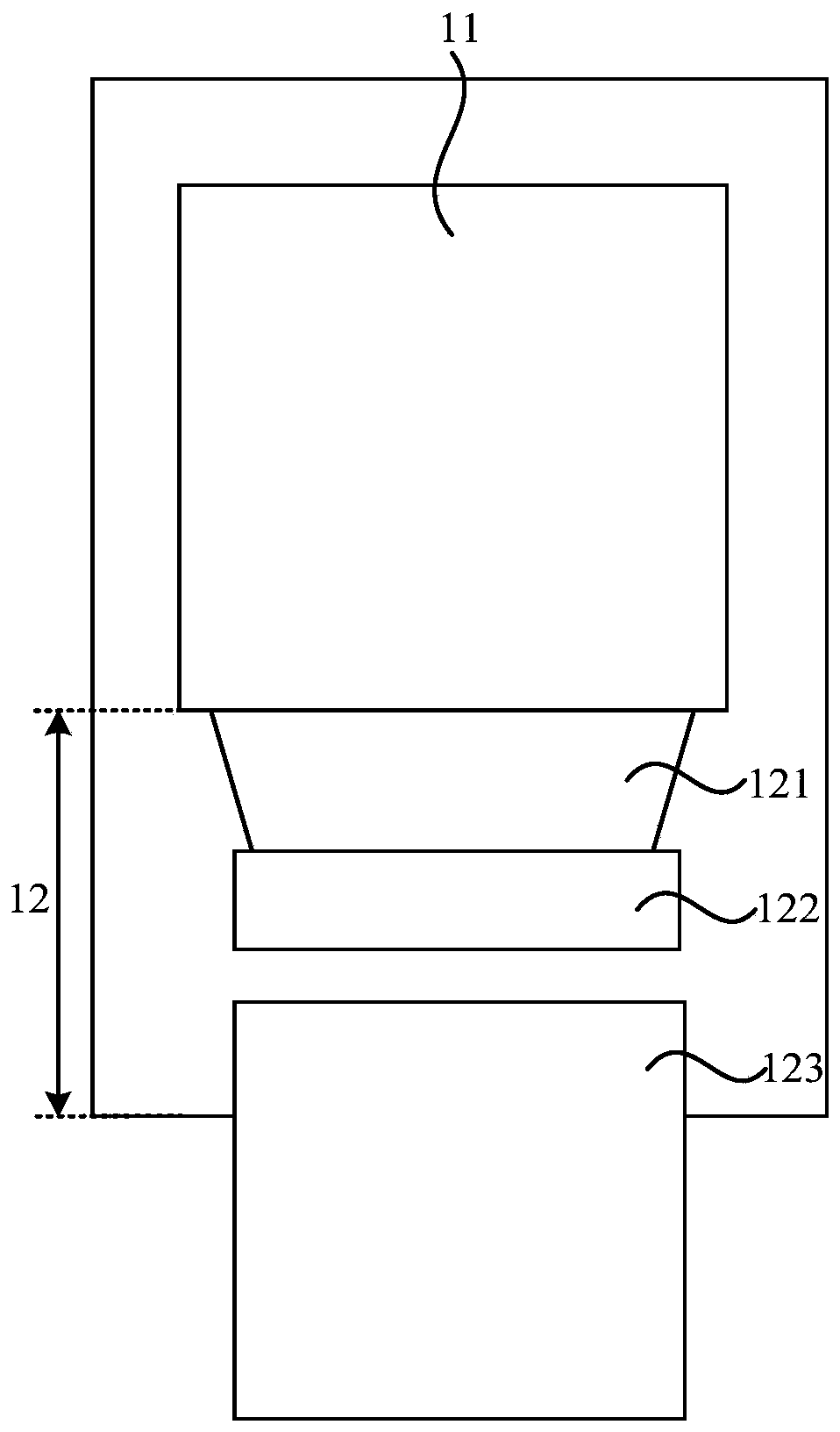
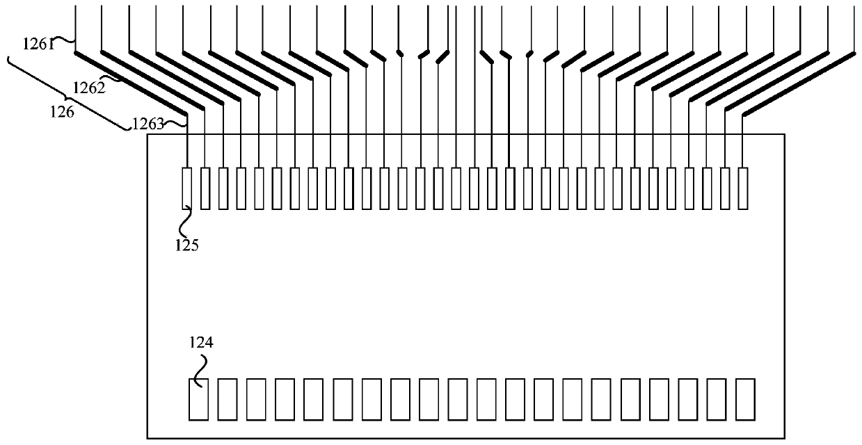
[0026] figure 1 is a structural schematic diagram of a display panel in the prior art, figure 2 It is a structural schematic diagram of output pads and fan-out wiring in the lower frame in the prior art, combined with figure 1 and figure 2 As shown, the display panel includes a display area 11 and a lower frame area 12 located on one side of the display area 11. The lower frame area 12 includes a fan-out area 121, an integrated driver chip 122 and a flexible circuit board 123. The lower frame area 12 also includes a plurality of The input pad 124 and a plurality of output pads 125 are bound to the integrated driver chip 122 . The fan-out area 121 is provided with a plurality of fan-out lines 126 , one end of the fan-out lines 126 is electrically connected to the output pad 125 , and the other end is electrically connected to the signal line in the display area AA (not shown in the figure). The fan-out wiring 126 in the prior art generally includes a first straight line po...


PUM


Abstract

The embodiment of the invention discloses a display panel and a display device, the display panel comprises a display area and a non-display area, and the display area comprises a plurality of signallines. The non-display area is provided with a first bonding pad binding area and a plurality of fan-out wires. The first bonding pad binding area is provided with a plurality of first bonding pads, the included angle between the extending direction of the first long edge of each first bonding pad and the first direction is an acute angle, and the included angle between the extending direction ofthe first short edge away from the display area and the second direction is an acute angle. The fan-out wire at least comprises a first sub fan-out wire, a first wiring part of the first sub fan-out wire is electrically connected with a signal line, and a second wiring part of the first sub fan-out wire is electrically connected with the first bonding pad. The included angle between the extendingdirection of the second wiring part and the first direction is an acute angle and is smaller than a preset included angle with the extending direction of the first long side. The oblique line part inthe first sub fan-out wire is directly connected with the first bonding pad, so that the fan-out wire can be translated towards the bonding pad side, and the lower frame of the display panel can be compressed.

Description

technical field [0001] Embodiments of the present invention relate to the field of display technology, and in particular, to a display panel and a display device. Background technique [0002] In the COG (chip on glass) panel in the prior art, the lower border of the display panel includes a fan-out wiring area, a driving chip bonding area and a flexible circuit board bonding area. For a high-resolution display panel, the fan-out routing area takes up a lot of space, and it is difficult to continue to compress the lower bezel with existing technical solutions, resulting in a larger lower bezel area, which is inconsistent with the development trend of full-screen display panels. Contents of the invention [0003] In view of this, embodiments of the present invention provide a display panel and a display device to compress the lower frame of the display panel to achieve a narrow frame design of the display panel. [0004] In a first aspect, an embodiment of the present inve...

Claims


Application Information

Patent Timeline
Patent Type & Authority Applications(China)
IPC IPC(8): G09F9/30
CPCG09F9/30
Inventor 简守甫曹兆铿秦锋秦丹丹王听海金慧俊姜炜张劼钟本顺
Owner SHANGHAI AVIC OPTOELECTRONICS
Why Eureka
Try Eureka