Communication type no-handheld steel bar strapping machine and steel bar strapping automation equipment

A strapping machine and communication-type technology, which is applied in the field of steel bar binding, can solve the problems of easy to cause accidents, inapplicability, and easy to touch the steel bars on the other side, so as to achieve the effect of ensuring stability, great flexibility and small size

Pending Publication Date: 2020-08-25
GUANGDONG SHUNDE HUAYAN ELECTRONICS TECH CO LTD
View PDF0 Cites 8 Cited by
  • Summary
  • Abstract
  • Description
  • Claims
  • Application Information

AI Technical Summary

Problems solved by technology

One of them is that the size of the steel bar binding machine is still large, and the structural layout of the whole machine is not suitable for automation. In the automatic binding, it is easy for the hand-held steel bar binding machine to touch the steel bars, such as steel bars with slab steel bars and facade steel bars. In the combined binding, due to the size of the hand-held steel bar binding machine, especially the protruding structure such as the handle, in the area where the steel bars on the panel and the facade steel bars intersect, the steel bar binding machine is easy to touch the steel bars on the other side when binding one of the steel bars , it is easy to cause accidents, or the local reinforcement nodes cannot be bound due to the large size of the reinforcement binding machine.
Similarly, if there is a combination of steel bars with inner and outer steel meshes, the hand-held steel bar binding machine on the automation equipment cannot bind the inner steel bars

Method used


Image

  • Communication type no-handheld steel bar strapping machine and steel bar strapping automation equipment
  • Communication type no-handheld steel bar strapping machine and steel bar strapping automation equipment
  • Communication type no-handheld steel bar strapping machine and steel bar strapping automation equipment

Examples


Embodiment 1

[0081] This embodiment discloses a communication-type non-handheld steel bar binding machine, which is small in size and suitable for automatic binding of various steel bar combinations. In addition, the non-handheld steel bar binding machine of this embodiment solves the problem The connection and fixation and communication problems of automation equipment make the steel bar binding machine and automation equipment better combined and synchronized.

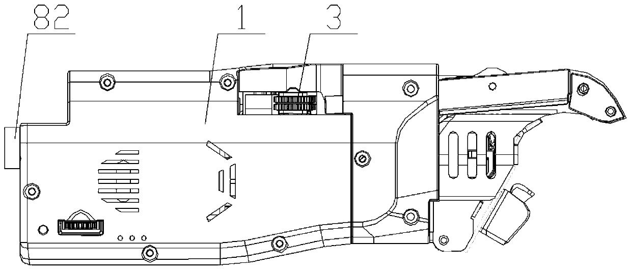
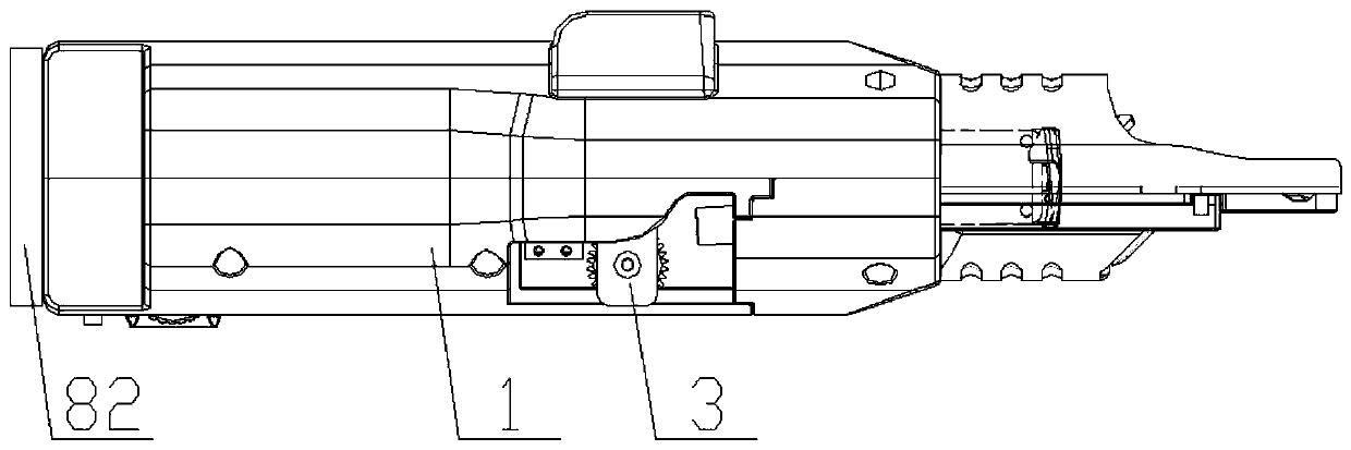
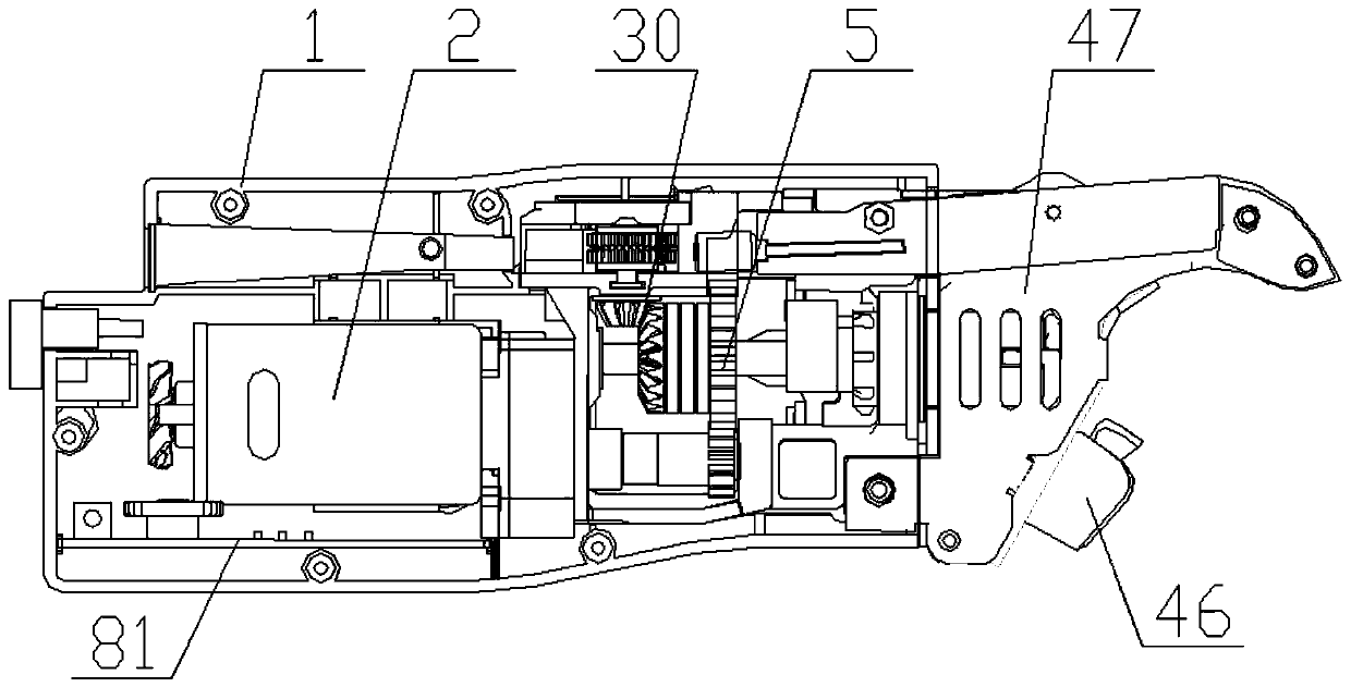
[0082] In this example, if figure 1 , 2 And as shown in 3a to 3c, the communication-type non-handheld steel bar binding machine includes a casing 1, a main control unit 81, a motor 2, a wire feeding mechanism 3, a wire twisting mechanism 6 and a cutting mechanism 4, wherein:

[0083] The main control unit is connected to the motor for driving the rotation of the motor;

[0084] The motor 2 connects the wire feeding mechanism 3, the wire twisting mechanism 6 and the cutting structure 4 through the transmission system 5, and cont...

Embodiment 2

[0128] This embodiment discloses an automatic steel bar binding device, including a host computer, a robot arm, and the communication-type hands-free steel bar binding machine described in Embodiment 1.

[0129] In this embodiment, the host computer is a control system of the robotic arm, or the host computer is connected to the control system of the robotic arm, and is used to control the movement of the robotic arm. In this embodiment, the upper computer can be directly a device in the mechanical arm as the control system, or it can be an external device of the mechanical arm. In the latter case, the upper computer is connected to the control system of the mechanical arm, and the control system of the mechanical arm Control the movement of the mechanical arm according to the signal received from the host computer.

[0130] The host computer is connected to the main control unit of the steel bar binding machine, and is used to send control instructions to the main control uni...

Embodiment 3

[0141] This embodiment discloses the steel bar binding method realized by the steel bar binding automation equipment shown in embodiment 2, including steps:

[0142] 1) The upper computer controls the movement of the mechanical arm, so that the steel bar binding machine on the mechanical arm moves to the steel bar binding node;

[0143] 2) When the steel bar binding machine reaches the position of the steel bar binding node, the upper computer sends a control command to the main control unit, and the main control unit controls the binding work of the steel bar binding machine according to the received control command. In this embodiment, after receiving the control command sent by the host computer, the main control unit controls the motor to work, so as to control the wire feeding mechanism, the cutting mechanism and the wire twisting mechanism to work respectively, so as to realize the functions of wire feeding, cutting and twisting. process, thereby realizing the reinforcem...


PUM


Abstract

The invention discloses a communication type no-handheld steel bar strapping machine and steel bar strapping automation equipment. The communication type no-handheld steel bar strapping machine comprises a machine shell, a main control unit, a motor, a wire feeding mechanism, a wire twisting mechanism and a cutting-off mechanism, wherein the machine shell is in a long strip type shape without a handheld portion, the motor is arranged inside the machine shell, and the wire feeding mechanism, the wire twisting mechanism and the cutting-off mechanism are all arranged inside the machine shell in the length direction of the machine shell to make the steel bar strapping machine be long in size only in the length direction. The communication type no-handheld steel bar strapping machine is small in structural volume and is suitable for performing steel bar strapping work in some relatively narrow areas in which plate face steel bars and vertical face steel bars intersect and steel bar combination sites where inner layer and outer layer steel bar nets exist, and the quality of steel bar strapping in these special sites is guaranteed; and meanwhile, the steel bar strapping automation equipment realized on account of the communication type no-handheld steel bar strapping machine can be suitable for automation strapping of various steel bar combinations and has the advantage of being highin steel bar strapping efficiency and quality.

Description

technical field [0001] The invention relates to the field of steel bar binding, in particular to a communication-type hands-free steel bar binding machine and automatic steel bar binding equipment. Background technique [0002] The prefabricated building is to transport some or all of the accessories to the construction site after being manufactured in the factory, and assemble the accessories through a reliable assembly method. With the characteristics of standardized design, factory production, assembly construction, integrated decoration, information management, intelligent application, etc., it is a representative of modern industrial production. [0003] With the general promotion and gradual deepening of prefabricated buildings, there are further requirements for the intelligence of prefabricated construction factories, and the automation of the production of prefabricated construction parts will be imminent. [0004] The accessories of prefabricated buildings are mai...

Claims


Application Information

Patent Timeline
Patent Type & Authority Applications(China)
IPC IPC(8): E04G21/12H04N7/18
CPCE04G21/123H04N7/18
Inventor 许长咏李移清吴加元罗泳杨
Owner GUANGDONG SHUNDE HUAYAN ELECTRONICS TECH CO LTD
Why Eureka
Try Eureka