A 0.4kv line interphase anti-collision device
An anti-collision and circuit technology, which is applied in the direction of devices that maintain the distance between parallel conductors, can solve problems such as burning out user equipment, voltage rise, and short-circuit of low-voltage lines, so as to avoid short-circuit of low-voltage lines, ensure reliability, and improve customer satisfaction degree of effect
- Summary
- Abstract
- Description
- Claims
- Application Information
AI Technical Summary
Problems solved by technology
Method used
Image
Examples
Embodiment 1
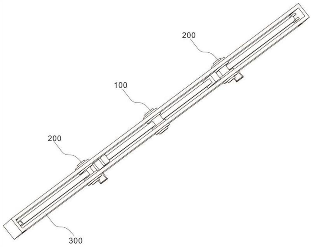
[0034] refer to Figure 1~6 , providing a schematic diagram of the overall structure of a 0.4kV line phase-to-phase anti-collision device, as shown in figure 1 , a 0.4kV line phase-to-phase anti-collision device includes a rotating unit 100 that allows some parts of the device to rotate, a bearing unit 200 that carries the rotating unit 100, an adjusting unit 300 and a limit unit 400, and an adjusting unit that regulates the device 300. The limiting unit 400 for limiting the rotating unit, the first rotating shaft 101 for rotating the rotating unit 100, and the first limiting block 102 for limiting the first rotating shaft 101, when the lines are arranged in rows , no need to change the shape of the device, let the line pass through the rotating unit 100, the carrying unit 200 and the adjusting unit 300, the limit unit 400 will limit the position of the rotating unit 100, so as to solve the problem of excessive sag of the 0.4kV line under the influence of wind and external for...
Embodiment 2
[0042] refer to figure 2 , this embodiment is different from the first embodiment in that: the rotating unit 100 for rotating some parts of the device includes a first rotating shaft 101 for rotating the rotating unit 100, and a first rotating shaft 101 for limiting the first rotating shaft 101. The limit block 102, the first installation block 103 enabling the first support rod 104 to be installed, the first support rod 104 for supporting, the support block 105 for supporting the adjustment unit 300, and the accommodation for the adjustment unit 300 The circular arc groove 106, the first through hole 107 to limit the circuit, the accommodation space N1, the ring mounting block 101-1 that allows the limit tooth 101-2 to be installed, and the limit to the first rotating shaft 101 The limiting tooth 101-2, when the circuit is arranged in a row, without changing the shape of the device, the circuit passes through the first through hole 107 in the rotating unit 100, the carrying ...
Embodiment 3
[0051] refer to figure 2 , This embodiment is different from the above embodiments in that: the carrying unit 200 carrying the rotating unit 100, the adjusting unit 300 and the limiting unit 400 includes a housing 201 that protects the device, and a first circuit that limits the circuit. The limit hole 202 and the second limit hole 203 that limit the adjustment unit 300, when the lines are arranged in rows, there is no need to change the shape of the device, so that the lines pass through the first through hole 107 in the rotation unit 100, the carrying unit 200 The first limit hole 202 and the adjustment unit 300 in the center, the limit unit 400 limits the rotation unit 100, so as to solve the problem that the sag of the 0.4kV line is too large, and the wire with a low sag will be entangled under the action of wind and external force Together, the low-voltage line is short-circuited, the voltage rises, and the problem of burning out the user's equipment occurs.
[0052] Pr...
PUM
 Abstract
Description
Claims
Application Information
 - R&D
- Intellectual Property
- Life Sciences
- Materials
- Tech Scout
- Unparalleled Data Quality
- Higher Quality Content
- 60% Fewer Hallucinations
Browse by: Latest US Patents, China's latest patents, Technical Efficacy Thesaurus, Application Domain, Technology Topic, Popular Technical Reports.
© 2025 PatSnap. All rights reserved.Legal|Privacy policy|Modern Slavery Act Transparency Statement|Sitemap|About US| Contact US: help@patsnap.com


