[0036] It should be understood that the specific embodiments described here are only used to explain the present invention, but not to limit the present invention.
[0037] The technical solutions in the embodiments of the present invention will be clearly and completely described below in conjunction with the accompanying drawings in the embodiments of the present invention. Obviously, the described embodiments are only a part of the embodiments of the present invention, rather than all the embodiments. Based on the embodiments of the present invention, all other embodiments obtained by those of ordinary skill in the art without creative work shall fall within the protection scope of the present invention.
[0038] It should be noted that all directional indications (such as up, down, left, right, front, back...) in the embodiments of the present invention are only used to explain the relationship between the components in a particular posture (as shown in the accompanying drawings). If the relative position relationship, movement situation, etc. change, the directional indication will change accordingly.
[0039] In addition, descriptions related to "first", "second", etc. in the present invention are only used for descriptive purposes, and cannot be understood as indicating or implying their relative importance or implicitly indicating the number of indicated technical features. Therefore, the features defined with "first" and "second" may explicitly or implicitly include at least one of the features. In addition, the technical solutions between the various embodiments can be combined with each other, but they must be based on what can be achieved by those of ordinary skill in the art. When the combination of technical solutions is contradictory or cannot be achieved, it should be considered that such a combination of technical solutions does not exist. , Is not within the protection scope of the present invention.
[0040] The present invention provides a wireless power supply circuit, which is used in a wireless power supply ultrasonic metering device. The wireless power supply ultrasonic metering device can be an ultrasonic water meter installed in each household, and can also be used for other electronic equipment whose working voltage meets the output voltage range. powered by.
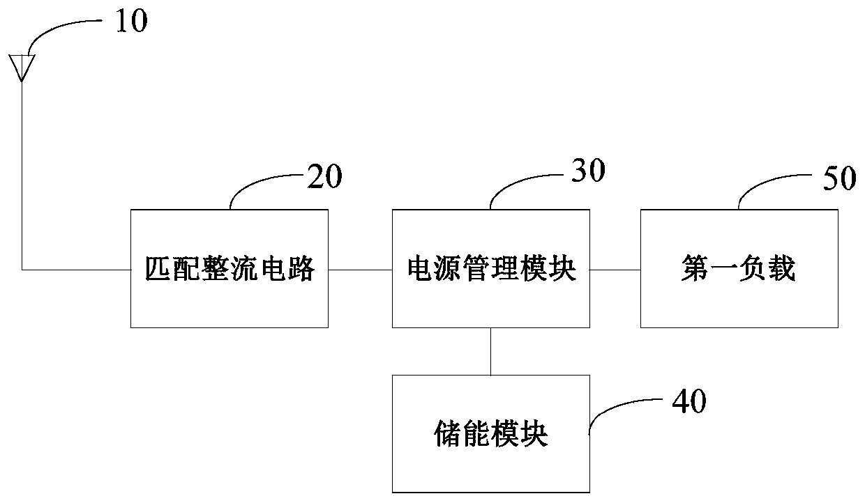
[0041] See figure 1 In an embodiment, the wireless power supply circuit includes a collection antenna 10, a matching rectification circuit 20, a power management module 30, and an energy storage module 40. The collection antenna 10 is connected to the input end of the matching rectification circuit 20, the output end of the matching rectification circuit 20 is connected to the input end of the power management module 30, the first output end of the power management module 30 is connected to the energy storage module 40, and the power management module 30 The second output terminal is connected to the first load 50. The collection antenna 10 is an electromagnetic wave collection antenna, which can receive electromagnetic waves in the surrounding space and transmit them to the matching rectifier circuit 20. In the matching rectification circuit 20, the electromagnetic waves in the space around the collecting antenna 10 can be fully collected through impedance matching, and the electromagnetic waves are rectified and converted into DC voltage to be output to the power management module 30. The power management module 30 has two output terminals. After the power management module 30 receives the DC voltage output by the matching rectifier circuit 20, it can supply power to the first load 50 through the second output terminal, and store energy through the first output terminal. The module 40 is charged. When the DC voltage received by the power management module 30 is lower than the minimum operating voltage of the power management module 30 or the voltage is unstable, it can also receive the power supply voltage output by the energy storage module 40, and process the power supply voltage as the first load 50 for power supply.
[0042] In this embodiment, the electromagnetic waves in the nearby space can be collected by the collecting antenna 10, and the corresponding DC voltage can be generated by the matching rectifier circuit 20. The DC voltage received by the power management module 30 is higher than the minimum operation of the power management module 30 At the time of voltage, the DC voltage can be processed to simultaneously supply power to the first load 50 and charge the energy storage module 40 through the DC voltage. When the DC voltage received by the power management module 30 cannot be converted into the power supply voltage of the first load 50, the power management module 30 may also receive the power supply voltage output by the energy storage module 40 to supply power to the first load 50, so that the first load 50 The load 50 can obtain long-term stable power supply to ensure the normal operation of the first load 50.
[0043] Further, refer to figure 1 with figure 2 The above-mentioned matching rectification circuit 20 may include a matching circuit 21 and a rectification circuit 22. The matching circuit 21 includes a first inductor L1 and a first capacitor C1. The first end of the first inductor L1 is connected to the collecting antenna 10, the second end of the first inductor L1 is connected to the input end of the rectifier circuit 22, and the The first terminal is connected to the first terminal of the first inductor L1, and the second terminal of the first capacitor C1 is grounded. The rectifier circuit 22 includes a second capacitor C2, a first diode D1, a second diode D2, and a third capacitor C3. The first end of the second capacitor C2 is connected to the second end of the first inductor L1, and the second end of the second capacitor C2 is respectively connected to the cathode of the first diode D1 and the anode of the second diode D2. The anode of the diode D1 is grounded, the cathode of the second diode D2 is connected to the input end of the power management module 30, the first end of the third capacitor C3 is connected to the cathode of the second diode D2, and the third capacitor C3 The second end is grounded. The matching circuit 21 can achieve impedance matching through the first inductor L1 and the first capacitor C1, so that the electromagnetic waves in the space around the collecting antenna 10 can be sufficiently collected and converted into AC voltage. The rectifier circuit 22 is a double voltage rectifier circuit, which can convert the alternating voltage collected and converted by the matching circuit 21 into a direct current voltage, and output it to the power management module 30 after being boosted twice. The electromagnetic wave collected by the collecting antenna 10 can be converted into a direct current voltage through the matching circuit 21 and the rectifying circuit 22.
[0044] Further, the aforementioned power management module 30 includes a fourth capacitor C4, a second inductor L2, and a power management chip U1. The first end of the second inductor L2 is connected to the cathode of the second diode D2, the second end of the second inductor L2 is connected to the input end of the power management chip U1, and the first output end of the power management chip U1 is connected to the energy storage module 40 is connected, the second output end of the power management chip U1 is connected to the first load 50, the first end of the fourth capacitor C4 is connected to the first end of the second inductor L2, and the second end of the fourth capacitor C4 is grounded. Among them, the second inductor L2 and the components in the power management chip U1 form a boost circuit, which can boost the received DC voltage to obtain the working voltage of the first load 50 and output it to the first load 50 for power supply. It can be output to the energy storage module 40 for power supply. The fourth capacitor C4 can play a role in filtering the AC signal to prevent the AC signal from interfering with the DC voltage.
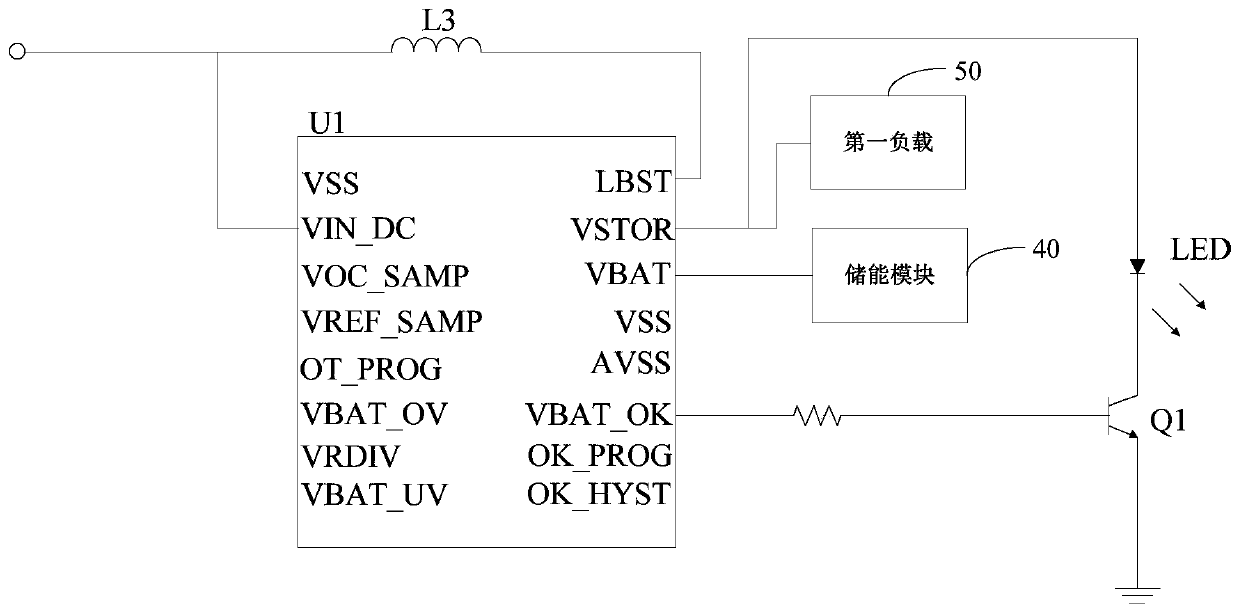
[0045] Further, the above-mentioned power management module 30 may further include a charging indication module, which includes a first light emitting diode LED and a first triode Q1. The anode of the first light emitting diode LED is connected to the second output terminal of the power management chip U1, the cathode of the first light emitting diode LED is connected to the collector of the first transistor Q1, the emitter of the first transistor Q1 is grounded, and the The base of a triode Q1 is connected to the third output terminal of the power management chip U1. The power management chip U1 can detect the power supply voltage of the energy storage module 40 when charging the energy storage module 40. When it is detected that the power supply voltage of the energy storage module 40 is higher than the preset voltage threshold, the energy storage module 40 can be determined The power is good, and the third output terminal of the power management chip U1 outputs a high level. The base of the first transistor Q1 switches to the on state after receiving the high level, and the first light-emitting diode LED is energized and emits light , To prompt the user that the energy storage module 40 is fully charged. Understandably, such as image 3 As shown, the base of the first transistor Q1 can be connected to the third output terminal of the power management chip U1 through a resistor to achieve a current limiting effect and prevent the first transistor Q1 from being damaged due to excessive current.
[0046] See image 3 A third inductor L3 may also be provided in the power management module 30, and the inductor connection end of the power management chip U1 is connected to the input end of the power management chip U1 through the third inductor L3. The third inductor L3 can detect whether the DC voltage meets the minimum operating voltage of the power management chip U1, thereby controlling the turning on and off of the power management chip U1.
[0047] Further, the above-mentioned power management chip U1 may be any one of a BQ25504 chip, an LTC3108 chip or an AEM10941 chip. Such as image 3 As shown, when the BQ25504 chip is selected as the power management chip U1, the VIN_DC pin, VBAT pin, VSTOR pin, VBAT_OK pin and LBST pin of the BQ25504 chip are the input terminal and the first pin of the power management chip U1. The output terminal, the second output terminal, the third output terminal and the inductor connection terminal. The minimum operating voltage of the BQ25504 chip is 0.13V, that is, when the DC voltage output by the rectifier circuit 22 is greater than 0.13V, the power management chip U1 can boost the DC voltage to charge the energy storage module 40 and supply power to the first load 50. It is understandable that the aforementioned energy storage module 40 may be a super capacitor or an energy storage rechargeable battery. The voltage range of the power supply voltage output by the energy storage module 40 may be 2.5V-5.25V. The power management chip U1 can adjust the power supply voltage and output the working voltage of the first load 50. When the first load 50 is an ultrasonic water meter, its working voltage may be 3.3V.
[0048] It should be noted that the power management chip U1 used in the above embodiment is a boost converter with a lower minimum operating voltage, a lower static operating current, and a higher chip voltage conversion efficiency, so that the signal received by the antenna 10 is collected The DC voltage after electromagnetic wave conversion can drive the power management chip U1 to realize energy harvesting and battery management functions.
[0049] The present invention also provides a wireless power supply ultrasonic measurement device. The wireless power supply ultrasonic measurement device includes a first load and a wireless power supply circuit connected to the first load. The first load may be an ultrasonic measurement device. The structure of the wireless power supply circuit can be referred to The foregoing embodiments will not be repeated here. Naturally, since the wireless power supply ultrasonic metering device of this embodiment adopts the technical solution of the above-mentioned wireless power supply circuit, the wireless power supply ultrasonic metering device has all the beneficial effects of the above-mentioned wireless power supply circuit.
[0050] The above are only optional embodiments of the present invention, which do not limit the scope of the present invention. Any equivalent structure or equivalent process transformation made by using the contents of the description and drawings of the present invention, or directly or indirectly applied to other related technologies In the same way, all fields are included in the scope of patent protection of the present invention.