Aircraft turbomachine with reduction gearset
A technology for turbines and reducers, which is applied in the lubrication of machines/engines, gas turbine devices, turbines/propulsion devices, etc., and can solve problems such as large diameters in the radial direction
- Summary
- Abstract
- Description
- Claims
- Application Information
AI Technical Summary
Problems solved by technology
Method used
Image


Examples
Embodiment Construction
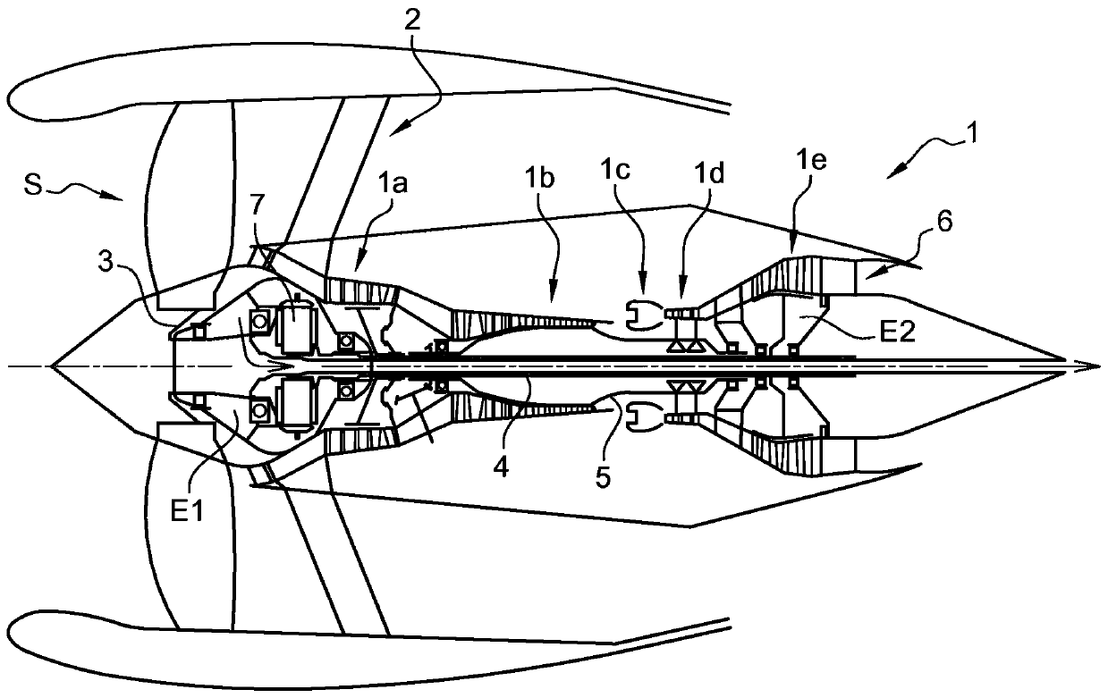
[0048] refer to figure 1, shows a turbine 1 with a speed reducer, which generally consists of a fan S, a low pressure compressor 1a, a high pressure compressor 1b, a combustion chamber 1c, a high pressure turbine 1d and a low pressure turbine 1e. The rotor of the high-pressure compressor 1b and the rotor of the high-pressure turbine 1d are connected by a high-pressure shaft 5 and form a high-pressure (HP) body with the high-pressure shaft 5 . The rotor of the low-pressure compressor 1a and the rotor of the low-pressure turbine 1e are connected by a low-pressure shaft 4 and form a low-pressure (LP) body. The shaft 3 of the fan S is driven by the LP shaft 4 via a reducer 7 .
[0049] The HP shaft 5 and the LP shaft 4 extend along an axis which is the axis of rotation of the turbine 1 . In the remainder of this description, the concepts "longitudinal" or "radial" and "inner" or "outer" are relative to this axis, and the concepts "upstream" and "downstream" refer to the flow. ...
PUM
 Abstract
Description
Claims
Application Information
 - R&D
- Intellectual Property
- Life Sciences
- Materials
- Tech Scout
- Unparalleled Data Quality
- Higher Quality Content
- 60% Fewer Hallucinations
Browse by: Latest US Patents, China's latest patents, Technical Efficacy Thesaurus, Application Domain, Technology Topic, Popular Technical Reports.
© 2025 PatSnap. All rights reserved.Legal|Privacy policy|Modern Slavery Act Transparency Statement|Sitemap|About US| Contact US: help@patsnap.com