Touch display device integrated on displayer

A touch display device and display technology, which is applied in the input/output process of instruments, data processing, electrical digital data processing, etc., can solve the problem of high cost, large size, and inability to develop and Market application and other issues, to achieve the effect of fast detection speed, simplified structure, and improved position detection ability

Inactive Publication Date: 2012-08-22
NANJING CEC PANDA LCD TECH
View PDF5 Cites 11 Cited by
  • Summary
  • Abstract
  • Description
  • Claims
  • Application Information

AI Technical Summary

Problems solved by technology

There are also some related On-Cell structure touch display devices, but they all have the following disadvantages: 1. The production of fine ITO layer pattern design is required, and the cost is high; 2. The size cannot be made very large, basically below 10 inches.
The above defects make the touch display device of On-Cell structure unable to obtain rapid development and market application

Method used


Image

  • Touch display device integrated on displayer
  • Touch display device integrated on displayer
  • Touch display device integrated on displayer

Examples


Embodiment 1

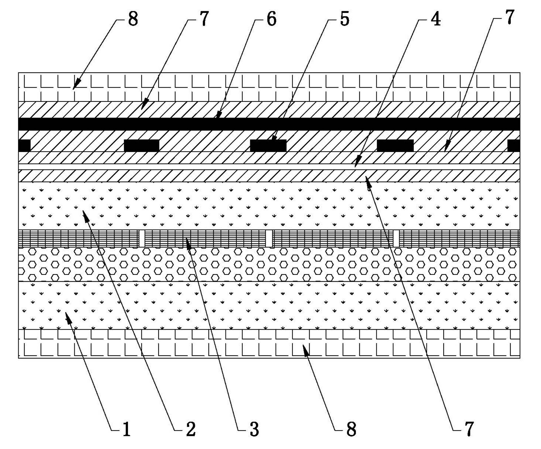
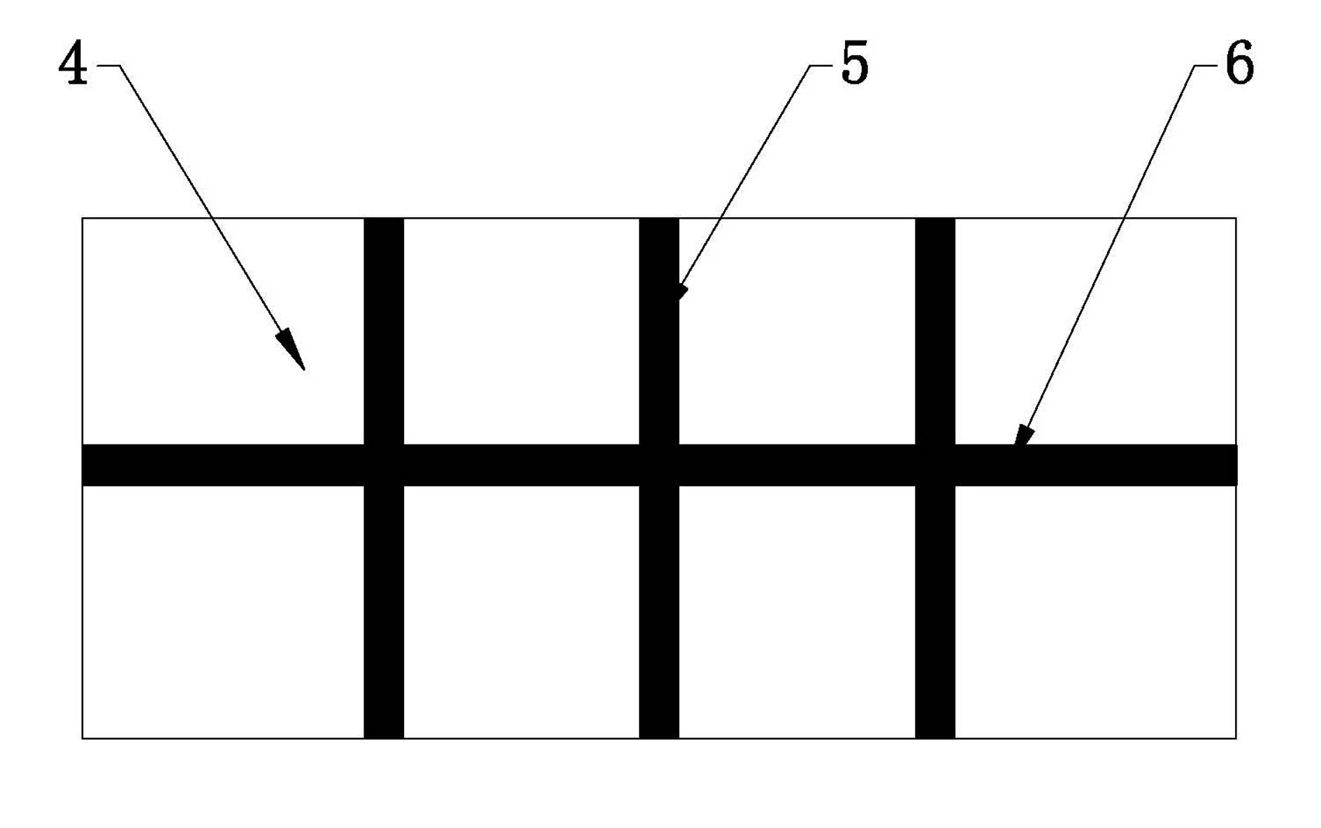
[0030] figure 1 For the integration of capacitive touch technology and liquid crystal display to form a touch screen, the On-Cell structure made on the glass substrate of the liquid crystal cell, such as figure 1As shown, the first substrate 1 is the array substrate of the liquid crystal display, and the second substrate 2 is the color filter substrate of the liquid crystal display. The space between the color filter substrate and the array substrate is filled with liquid crystal, and the surrounding is sealed with Seal. For a color liquid crystal display, RGB color layers 3 composed of red, green and blue color resist patterns are distributed on the color filter substrate, and corresponding pixel units are arranged at the corresponding positions of the array substrate; on the upper side of the color filter substrate Distributed planar transparent electrode layer 4 and criss-cross first metal layer 5, second metal layer 6, between planar transparent electrode layer 4 and first...

Embodiment 2

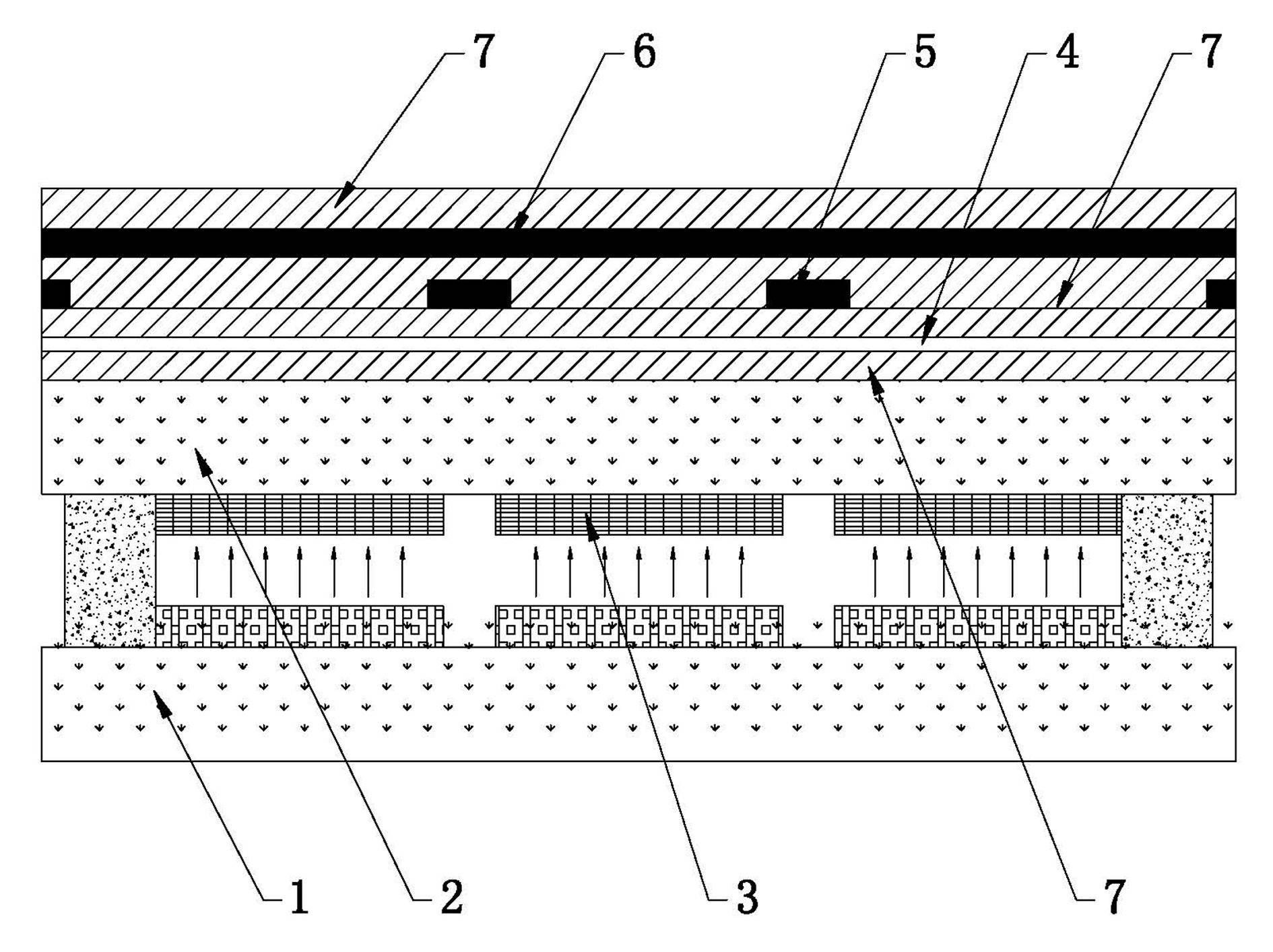
[0032] figure 2 It is a structural diagram of integrating touch technology on a field emission display. exist figure 2 Among them, the first substrate 1 is a cathode substrate with an electron source, and the second substrate 2 is an anode substrate with phosphor powder. The RGB color resist layer 3 is arranged on the lower side of the second substrate 2, and the upper side of the second substrate 2 is distributed with the planar transparent electrode layer 4 and the first metal layer 5 and the second metal layer 6 which criss-cross. A transparent insulating layer 7 is also provided between the transparent electrode layer 4 and the first metal layer 5 , and between the first metal layer 5 and the second metal layer 6 , and the black matrix may not be used between the RGB color resist layers 3 . in addition figure 1 In addition, a transparent insulating layer 7 is provided between the second substrate 2 and the planar transparent electrode layer 4 and outside the second me...


PUM


Abstract

The invention discloses a touch display device integrated on a displayer, which comprises a first substrate (1) and a second substrate (2) integrating an electric control unit, wherein the first substrate (1) and the second substrate (2) are oppositely arranged, a red, green and blue (RGB) color layer (3) is arranged on one side of the second substrate (2) facing to the first substrate (1), a faceted transparent electrode layer (4) and a first metal layer (5) and a second metal layer (6) which are arranged in staggered mode are sequentially arranged on one side of the second substrate (2) back on to the first substrate (1), and the first metal layer (5) is located between the faceted transparent electrode layer (4) and the second metal layer (6). The touch display device integrated on the displayer conducts position detection of touch points through the faceted transparent electrode layer and metal electrodes, avoids optical interference caused by patterning of the transparent electrode layer, greatly improves capability of touch point position detection, has the advantages of being fast in detection and low in driving cost, and can achieve production of high-fineness and large-size touch panels.

Description

technical field [0001] The invention relates to the technical field of integration of a touch panel and a flat panel display device, in particular to a touch display device integrated on a display. Background technique [0002] The development direction of touch technology is low cost, high yield, large size, high reliability and so on. In order to achieve this goal, in terms of process technology, ITO Sensor, Cover lens and even TFT can be integrated together to reduce production costs, make the thickness thinner, and avoid the problem of poor bonding. In terms of material technology, organic or inorganic alternative materials for ITO can be developed, flexible film and substrate technology can be mastered, or new plastic materials can be used on Cover Lens materials to replace more expensive reinforced glass or PMMA plastic plates. In terms of structural technology, the structures of Out-Cell, On-Cell and In-Cell have been developed. [0003] Out-Cell technology is main...

Claims


Application Information

Patent Timeline
Patent Type & Authority Applications(China)
IPC IPC(8): G06F3/044
Inventor 马群刚
Owner NANJING CEC PANDA LCD TECH
Why Eureka
Try Eureka