Eureka AIR delivers breakthrough ideas for toughest innovation challenges, trusted by R&D personnel around the world.

Centrifugal pendulum device with a diaphragm spring for generating frictional resistance, clutch plate, and powertrain

A technology of centrifugal force pendulum and disk spring, which is applied in the field of drive system and can solve the problems of contact element wear and other problems

Active Publication Date: 2020-08-21
SCHAEFFLER TECH AG & CO KG
View PDF9 Cites 0 Cited by
  • Summary
  • Abstract
  • Description
  • Claims
  • Application Information

AI Technical Summary

Problems solved by technology

This leads to increased wear on the contact elements

Method used


Image

  • Centrifugal pendulum device with a diaphragm spring for generating frictional resistance, clutch plate, and powertrain
  • Centrifugal pendulum device with a diaphragm spring for generating frictional resistance, clutch plate, and powertrain
  • Centrifugal pendulum device with a diaphragm spring for generating frictional resistance, clutch plate, and powertrain

Examples


Embodiment approach 1

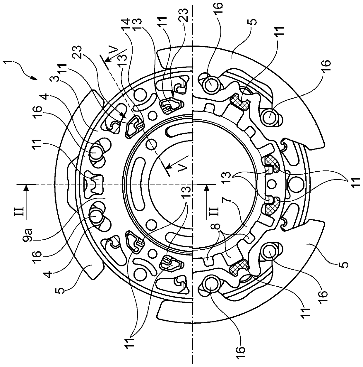
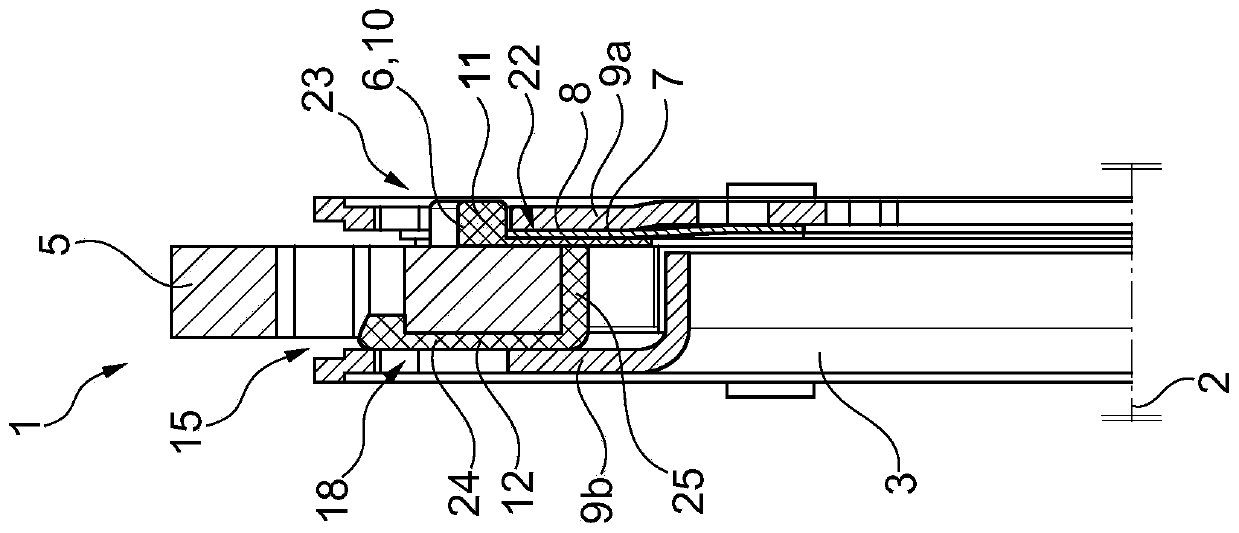
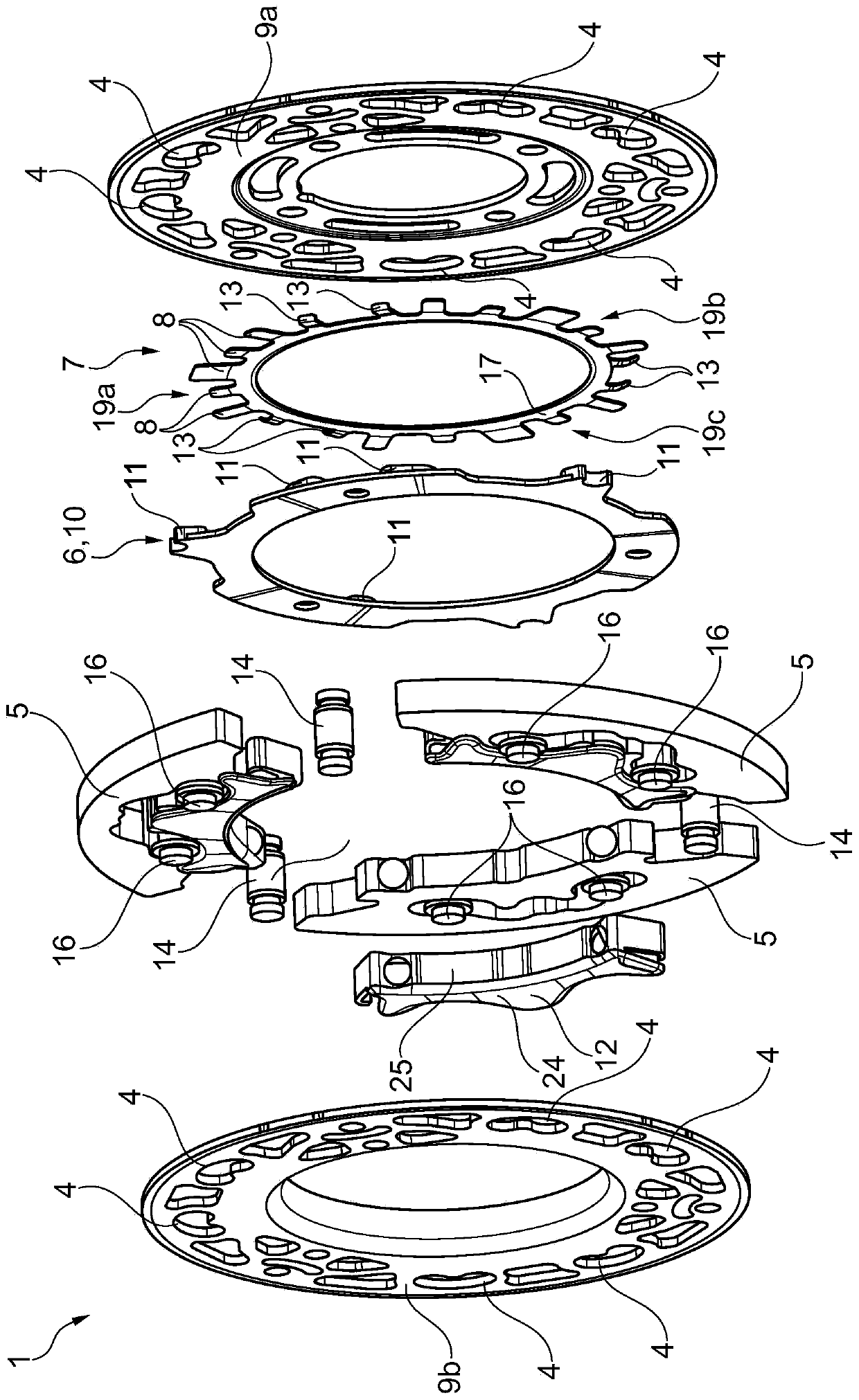
[0063]The friction device 18 in the centrifugal pendulum 1 has the function of reducing the large vibration angle of the pendulum mass 5 . The disk spring 7 serves here as an energy store / force source. The disk spring 7 is arranged between the pendulum mass 5 and the flatter of the two flanges (first support area 9a (smaller axial extent than the second support area 9b)) and projects radially inwards into the gap 22 between the two flanges 9a, 9b. This makes use of this space in order to achieve a function-optimized spring characteristic curve. The disc spring 7 has a plurality of outer tongues 8 , 13 . The more strongly curved outer tongue 13 has the function of centering the disk spring 7 in the centrifugal pendulum 1 , positioning the disk spring 7 during assembly of the centrifugal pendulum and transmitting force in the circumferential direction to the flange 9 a. The tongue 8 which is only slightly bent transmits the spring force via the friction rings 6 , 10 to the in...

Embodiment approach 2

[0065] Another conceivable variant is that the friction ring 6 is made of sheet metal or is embodied as a support disk (support element 26 ).

Embodiment approach 3

[0067] Another conceivable variant is to arrange annular friction rings 6 , 10 on both sides of pendulum mass 5 .


PUM


Abstract

The invention relates to a centrifugal pendulum device (1) for a powertrain of a motor vehicle, comprising: a support (3) which is rotatable about an axis of rotation (2); a pendulum mass (5), which is received on the support (3) so as be able to swing along a guide path (4), a restoring movement directed oppositely to an engine irregularity being produced by the pendulum mass (5) during operation; a contact element (6) bearing against the pendulum mass (5), which contact element (6) is used to produce a frictional resistance that prevents relative motion between the pendulum mass (5) and thesupport (3); and a spring washer (7), which preloads the contact element (6) towards the pendulum mass (5) in an axial direction of the axis of rotation (2), the spring washer (7) being formed as a diaphragm spring (7) equipped with a plurality of spring tongues (8). The invention additionally relates to a clutch plate (20) for a friction clutch of a motor vehicle comprising said centrifugal pendulum device (1), and to a powertrain for a motor vehicle, likewise comprising said centrifugal pendulum device (1).

Description

technical field [0001] The present invention relates to a centrifugal force pendulum device (also called centrifugal force pendulum for short), which is used for the drive train of motor vehicles (such as passenger vehicles, trucks, buses or other commercial vehicles). The centrifugal force pendulum device has: A rotating bracket; a pendulum mass mounted on the bracket so as to be able to pivot along a slide track, wherein a return moment is generated by the pendulum mass during operation against unevenness in rotation; the contact element abutting against the pendulum mass, so The contact element (directly or indirectly) produces a frictional resistance against the relative movement between the pendulum mass and the support; and a spring disk pretensions the contact element towards the pendulum mass in the axial direction of the axis of rotation. The invention also relates to a clutch disc of a friction clutch for a motor vehicle and a drive train for a motor vehicle, each ha...

Claims


Application Information

Patent Timeline
IPC IPC(8): F16F15/14
CPCF16F15/145F16D13/585F16D2013/586
Inventor E·弗朗茨A·鲁施J·马特斯B·罗伊特
Owner SCHAEFFLER TECH AG & CO KG
Why Eureka
Eureka Blog
Learn More