Miniature in-ear imaging device

An imaging device and miniature technology, applied in otoscope, endoscope, medical science, etc., can solve the problems of real-time evaluation of the stability of implanted artificial ossicle prosthesis, narrow operation and field of view, and inexperienced surgeons. To achieve the effect of avoiding poor rehabilitation effect, reducing purchase cost and patient economic burden, and good application effect

Pending Publication Date: 2020-08-25
THE FIRST AFFILIATED HOSPITAL OF ARMY MEDICAL UNIV
View PDF0 Cites 2 Cited by
  • Summary
  • Abstract
  • Description
  • Claims
  • Application Information

AI Technical Summary

Problems solved by technology

However, the position of the middle ear is deep, and the scope of surgery and field of view is narrow. It is impossible to evaluate the stability of the artificial ossicle prosthesis in real time during the operation.
[0003] At present, the judgment of the stability of implanted artificial ossicles is mainly based on the subjective judgment of the operator's vision and sense of touch during middle ear surgery, or the use of indirect methods such as AABR / ASSR middle ear surgery using loudspeaker to perform hearing monitoring during surgery to detect implants. The stability of the implanted ossicles, but the inexperience of the operator, electromagnetic field interference, background noise, external auditory canal packing, etc. affect the judgment effect
At present, there is no technology at home and abroad that can meet the real-time observation during operation to ensure the stability of artificial auditory ossicle placement during operation.

Method used


Image

  • Miniature in-ear imaging device
  • Miniature in-ear imaging device

Examples


Embodiment Construction

[0033] The present invention will be described in further detail below in conjunction with the accompanying drawings.

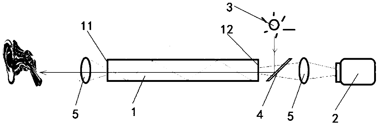
[0034] A miniature in-ear imaging device, comprising an image transmission component 1, an illumination component, an imaging module 2 and a display, the image transmission component 1 includes a transmission channel, the two ends of the transmission channel are respectively a detection end 11 and an observation end 12, and the illumination component is arranged on On the side of the observation end 12 of the transmission channel, the lighting assembly includes an illumination source 3 and a reflector 4. The reflector 4 is arranged on the extension direction of the transmission channel and is inclined relative to the extension direction. The reflector 4 is located on the irradiation direction of the illumination source 3 and will The light is reflected into the transmission channel; the imaging module 2 is arranged on the other side of the mirror 4 opposite to...


PUM


Abstract

The invention discloses a miniature in-ear imaging device, and relates to the field of medical detection equipment. According to the specific scheme, the miniature in-ear imaging device comprises an image transmission assembly, a lighting assembly, an imaging module and a display. The image transmission assembly includes a transmission channel, and the two ends of the transmission channel are correspondingly a detection end and an observation end, the lighting assembly is arranged on one side of the observation end of the transmission channel, the lighting assembly includes a lighting light source and a reflector, the reflector is arranged in the extension direction of the transmission channel and is arranged obliquely relative to the extension direction, and the reflector is located in the lighting direction of the lighting light source and reflects light into the transmission channel. The imaging module is arranged on the other side, opposite to the transmission channel, of the reflector, and the imaging module is connected with the display in a signal mode. The miniature in-ear imaging device uses flexible optical fibers, so that the detection effect is improved; the miniature in-ear imaging device can record videos, and the subsequent processing and reference the videos in the later stage is facilitated; and the miniature in-ear imaging device has a good application effectand is further highly economical.

Description

technical field [0001] The invention relates to the field of medical detection equipment, more specifically, it relates to a miniature ear imaging device. Background technique [0002] Middle ear surgery implantation of artificial ossicle prosthesis is the main treatment for the destruction of auditory ossicles caused by otitis media. However, the position of the middle ear is deep, and the scope of surgery and field of view is narrow. Clinically, it is impossible to evaluate the stability of the artificial ossicle prosthesis in real time during the operation. [0003] At present, the judgment of the stability of implanted artificial ossicles is mainly based on the subjective judgment of the operator's vision and sense of touch during middle ear surgery, or the use of indirect methods such as AABR / ASSR middle ear surgery using loudspeaker to perform hearing monitoring during surgery to detect implants. The stability of the implanted ossicles, but the inexperience of the ope...

Claims


Application Information

Patent Timeline
Patent Type & Authority Applications(China)
IPC IPC(8): A61B1/227A61B1/04A61B1/07
CPCA61B1/00045A61B1/00096A61B1/04A61B1/0684A61B1/07A61B1/227
Inventor 袁伟陈小玲贾立峰陈知己陈林邹文进唐峰
Owner THE FIRST AFFILIATED HOSPITAL OF ARMY MEDICAL UNIV
Why Eureka
Try Eureka