
Optic nerve clamp for optic nerve injury model

A technology for optic nerve injury and optic nerve, applied in veterinary instruments, veterinary surgery, medical science, etc., can solve the problem that the degree of injury cannot be quantified well, and achieve the effect of stable clamping, convenient operation and high reliability

Pending Publication Date: 2020-08-25
UNIV OF ELECTRONICS SCI & TECH OF CHINA
View PDF0 Cites 0 Cited by
  • Summary
  • Abstract
  • Description
  • Claims
  • Application Information

AI Technical Summary

Problems solved by technology

Establish the experimental animals used to include rabbits, rats, mice, guinea pigs, cats, etc. There are many ways to establish animal models: (1) the animal model of optic nerve damage caused by the clamping method. This method is to expose the optic nerve by surgical incision. The optic nerve is injured by clamping the optic nerve; its biggest disadvantage is that the degree of injury cannot be quantified; in pursuit of building a safe and effective optic nerve injury model, the researchers hope to build an animal model of clamping the optic nerve injury by improving the previous experimental methods , Through previous experiments, the basic steps of the experiment have been mastered. The outstanding problem is the need for a clamping instrument that can quantitatively damage the optic nerve.
In the prior art, there is no clamp with quantitative force,

Method used


Image

  • Optic nerve clamp for optic nerve injury model
  • Optic nerve clamp for optic nerve injury model
  • Optic nerve clamp for optic nerve injury model

Examples


Embodiment 1

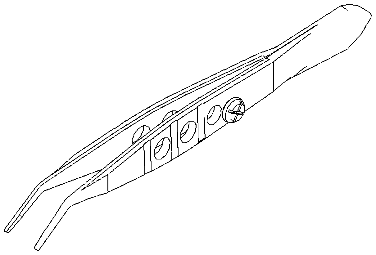
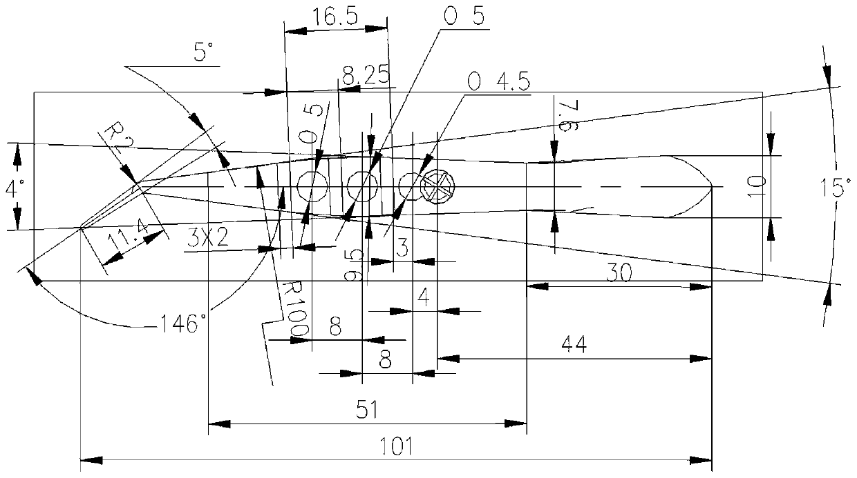
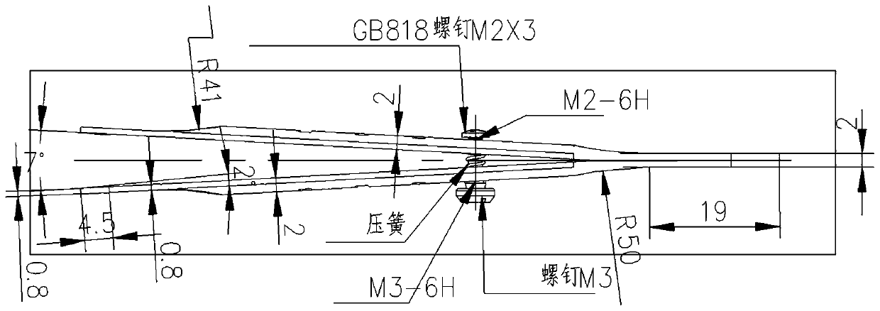
[0016] An optic nerve jig for an optic nerve injury model, the total length of the jig is 101mm; the jig includes: two strip-shaped rigid clips with completely symmetrical structures, and the surfaces of the two clips are subjected to surface heat treatment of HRC44-46; Each clip includes: root, middle, and tip; the length of the root is 30mm, the roots of the two clips are welded together, and the thickness of the welded joint is 2mm, and the end of the root is treated with an inverted arc. The width of the width is 10mm, and the width of the connection with the middle part is 7.6mm; the middle part is the force application area, and the force is applied to clamp the fixture. The length of the middle part is 51mm, and the thickness is 2mm. 50mm rounded corners, the middle part is the shape of the middle width of the two houses, the width of the widest part of the middle part is 9.5mm, and the width of the middle part gradually widens from the connection between the middle part...

Embodiment 2

[0019] The fixture includes: two strip-shaped rigid clips with completely symmetrical structures, and the surfaces of the two clips are subjected to HRC44-46 surface heat treatment; each clip includes: root, middle, and tip; the root of the two clips Welded together, the middle part is the force application area, the force is applied to clamp the fixture, the tip is in a separated state when no force is applied, and the end of the tip is bent, which is characterized in that the inner surfaces of the root, middle and tip are flush; two pieces The middle part of the clip is provided with three through holes corresponding to the deformation direction of the clip when clamping with force; each through hole is provided with a screw and a nut, and when the screw and the nut are threaded, the head of the screw and the nut are located On the outside of the two clips, the clamp clamps the optic nerve through the screw nut screwing in; a compression spring is arranged between the screw r...


PUM


Abstract

The invention discloses an optic nerve clamp for an optic nerve injury model, and belongs to the field of clamping devices. The clamp comprises two strip-shaped rigid clamping pieces which are completely symmetrical in structure, wherein each clamping piece comprises a root portion, a middle portion and a tip portion; the root portions of the two clamping pieces are welded together; the middle portions of the two clamping pieces are force application areas; force is applied to enable the clamp to conduct clamping; and the tip portions are in a separated state when the clamp is not stressed, and the tail ends of the tip portions are bent. The clamp is characterized in that three holes are correspondingly formed in each of the middle portions of the two clamping pieces in the deformation direction of the clamping pieces when the clamping pieces receive an applied force and conduct clamping; a screw rod and a screw cap are arranged in each hole; when the screw rods and the screw caps arein threaded connection, both the heads of the screw rods and the screw caps are located on the outer sides of the two clamping pieces; and the clamp clamps an optic nerve through screwing-in of the screw caps on the screw rods. The clamp has the advantages of stable clamping, high reliability, capability of conducting quantitative injury on optic nerves and convenience in operation by a user.

Description

technical field [0001] The invention belongs to the field of clamping devices. Background technique [0002] Traumatic optic neuropathy, also known as traumatic optic nerve injury, is a lesion that causes severe visual impairment due to eye or head trauma, causing vision loss, color vision disturbance, visual field defect, or even complete loss of vision, including direct traumatic optic neuropathy and The latter is more common in indirect traumatic optic neuropathy. Regarding the study of animal models, some scholars at home and abroad have done this work. Establish the experimental animals used to include rabbits, rats, mice, guinea pigs, cats, etc. There are many ways to establish animal models: (1) the animal model of optic nerve damage caused by the clamping method. This method is to expose the optic nerve by surgical incision. The optic nerve is injured by clamping the optic nerve; its biggest disadvantage is that the degree of injury cannot be quantified; in pursuit...

Claims


Application Information

Patent Timeline
Patent Type & Authority Applications(China)
IPC IPC(8): A61D1/00
CPCA61D1/00
Inventor 王欢陈辉
Owner UNIV OF ELECTRONICS SCI & TECH OF CHINA
Learn More