Ultrasonic cleaning treatment method for manufacturing optical protective lenses

A technology for optical protection and cleaning treatment, applied in cleaning methods and utensils, cleaning methods using liquids, chemical instruments and methods, etc., can solve problems such as easy adhesion, reduced transparency of optical protective lenses, and difficulty in cleaning.

Active Publication Date: 2021-06-04
江西特莱斯光学有限公司
View PDF0 Cites 0 Cited by
  • Summary
  • Abstract
  • Description
  • Claims
  • Application Information

AI Technical Summary

Problems solved by technology

[0004] In the existing optical protective lenses, after being worn for a period of time, stains will adhere to the surface and be difficult to clean, which reduces the transparency of the optical protective lenses and affects the wearing effect. It is often necessary to use ultrasonic waves to clean the optical protective lenses. Optical protective lenses During the cleaning process, after the optical protective lens is cleaned in the ultrasonic cleaning pool, it is directly taken out and drained, and when the cleaning liquid in the ultrasonic cleaning pool cleans the last optical protective lens, there are stains floating in the cleaning liquid, and the stains are easy It adheres to the surface of the optical protective lens, so that after the optical protective lens is drained, there are still some stains, which affects the cleaning effect of the optical protective lens

Method used


Image

  • Ultrasonic cleaning treatment method for manufacturing optical protective lenses
  • Ultrasonic cleaning treatment method for manufacturing optical protective lenses
  • Ultrasonic cleaning treatment method for manufacturing optical protective lenses

Examples


Embodiment Construction

[0034] The embodiments of the present invention will be described in detail below with reference to the accompanying drawings, but the present invention can be implemented in many different ways defined and covered by the claims.

[0035] In order to make the technical means, creative features, goals and effects achieved by the present invention easy to understand, the present invention will be further described below in conjunction with specific illustrations.

[0036] It should be noted that when an element is said to be "fixed" to another element, it may be on the other element or there may be an intervening element. When an element is referred to as being "connected to" another element, it can be directly connected to the other element or intervening elements may also be present. The terms "vertical", "horizontal", "left", "right" and similar expressions are used herein for the purpose of illustration only and do not represent the only embodiment.

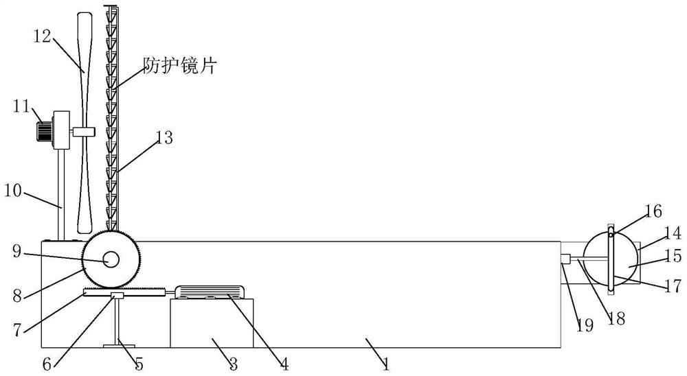
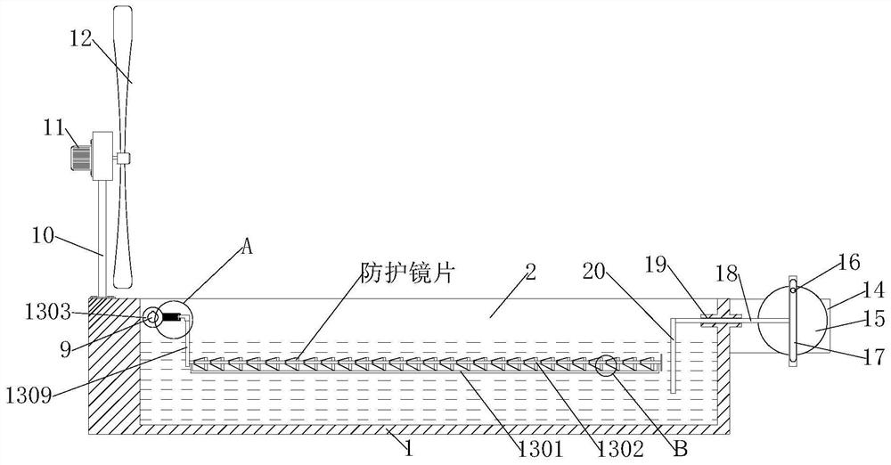
[0037] see Figure 1-8 ...


PUM


Abstract

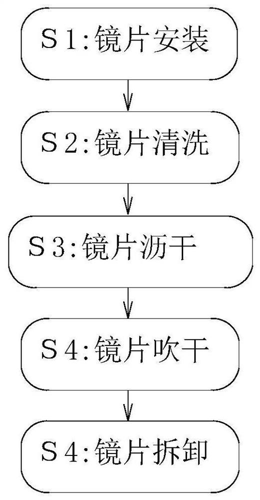
The invention discloses an ultrasonic cleaning treatment method for manufacturing optical protective lenses, and relates to the technical field of metallurgical processing. The ultrasonic cleaning treatment method for manufacturing optical protective lenses is completed by the cooperation of an ultrasonic cleaning treatment device for manufacturing optical protective lenses. The cleaning treatment device includes a cleaning machine casing, and an ultrasonic cleaning pool with an opening facing upwards is provided on the top of the cleaning machine casing. The present invention reciprocates and slightly moves each piece of optical protective lens in the cleaning pool, so that the ultrasonic waves emitted by the ultrasonic generator in the ultrasonic cleaning pool can act on the surface of the optical protective lens through different angles. During the fretting process of the optical protective lens, the resistance of the cleaning liquid is used to impact the stains adhering to the optical protective lens to clean the stains on the optical protective lens.

Description

technical field [0001] The invention relates to the technical field of protective lens processing, in particular to an ultrasonic cleaning treatment method for manufacturing optical protective lenses. Background technique [0002] Ultrasonic cleaning is to use the cavitation, acceleration and direct flow of ultrasonic waves in the liquid to directly and indirectly affect the liquid and dirt, so that the dirt layer is dispersed, emulsified, and peeled off to achieve the purpose of cleaning. In the currently used ultrasonic cleaners, cavitation and direct flow are more widely used. [0003] Optical protective lens is a kind of transparent lens that is extruded by resin and other materials. The lens has various structures. Because resin has strong plasticity, plastic materials such as resin are often used to make curved optical protective lenses. Protective lenses have the advantages of being beautiful and comfortable to wear. [0004] In the existing optical protective lense...

Claims


Application Information

Patent Timeline
Patent Type & Authority Patents(China)
IPC IPC(8): B08B3/12B08B3/10B08B3/02B08B13/00F26B21/00
CPCB08B3/022B08B3/10B08B3/123B08B13/00F26B21/001
Inventor 李维其李治倪娅丹高亚芳
Owner 江西特莱斯光学有限公司
Why Eureka
Try Eureka