Method for cleaning floor heating pipes

A technology for cleaning floor heating pipes and pipes, applied in the field of floor heating pipe cleaning, can solve the problem of not heating the floor, and achieve the effects of prolonging the service life, short cleaning time, and good heat dissipation function.

Inactive Publication Date: 2013-05-01
山西省第二建筑工程公司
View PDF5 Cites 9 Cited by
  • Summary
  • Abstract
  • Description
  • Claims
  • Application Information

AI Technical Summary

Problems solved by technology

[0005] In order to overcome the problem that the floor heating is not hot due to the blockage and scaling in the pipeline afte

Method used


Image

  • Method for cleaning floor heating pipes
  • Method for cleaning floor heating pipes

Examples


Embodiment Construction

[0016] The present invention will be further described below in conjunction with the accompanying drawings and embodiments.

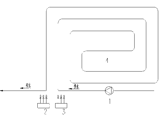
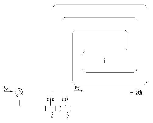
[0017] The first flushing: first open the floor heating water separator 2 and the water collector 3 respectively, and the flushing is divided into two steps. The first step adopts the method of backwashing ( figure 1 As shown), that is, use a high-pressure water pump to connect the hot water return pipe of the floor heating, connect the water supply pipe to the indoor floor drain, set the pressure of the high-pressure water pump to twice the operating pressure of the floor heating, remove the slime in the pipe, and rinse for 8 minutes. The second step adopts the method of positive washing ( figure 2 As shown), the high-pressure water pump is connected to the hot water supply pipe of the floor heating, and the return pipe is connected to the indoor floor drain. When the water pipe flows out of clean water, stop the first flushing of the pipe.

[0018]...


PUM


Abstract

The invention provides a method for cleaning floor heating pipes. The method is characterized by comprising the following steps of: firstly flushing, removing loams in the pipes, then soaking the pipes by cleaning fluid, dissolving rust and scale in the pipe, and finally Secondarily flushing the pipe. Through the method, the cleaning is safe and convenient, the cleaning time is short, the cleaning effect is excellent, the cleaning cost is low, the excellent radiation function of the pipe after cleaning can be kept, the service life of the floor heating pipe can be prolonged, no harm to human body is generated in the cleaning process, the equipment is not corroded, and the environment is not affected.

Description

technical field [0001] The invention relates to a method for cleaning floor heating pipes. Background technique [0002] At present, after the known floor heating pipeline is used for a period of time, a large amount of slime, bacteria and calcium and magnesium ion scale (carbonate, sulfate, phosphate of calcium and magnesium) will be produced on the inner wall of the pipeline, which will adhere to the inner wall of the pipeline to form a pipeline. Blockage will lead to poor water circulation and insufficient heat dissipation, which will seriously affect the heating temperature and effect. [0003] Some data show that after one year of floor heating, every 1mm of dirt on the inner wall of the floor heating pipe will cause the temperature in the heating room to drop by 5-6°C. This not only affects the normal use of floor heating, but also causes a waste of energy. [0004] If the geothermal heating system is not cleaned effectively for a long time, the geothermal heati...

Claims


Application Information

Patent Timeline
IPC IPC(8): F28G9/00
Inventor 王巧利刘志伟王国平王博雅任勇刚
Owner 山西省第二建筑工程公司
Why Eureka
Try Eureka