Surface treatment method of metal member and cleaning nozzle

Inactive Publication Date: 2011-03-03
HITACHI CABLE
View PDF10 Cites 11 Cited by
  • Summary
  • Abstract
  • Description
  • Claims
  • Application Information

AI Technical Summary

Benefits of technology

[0068]According to one embodiment of the invention, a surface treatment method of a metal member and a surface treatment device that are capable of using self-generation two fluids that can be heated up to a temperature at which a necessary cleaning power can be obtained, completing the cleaning treatment in a short time, and preventing the VOC from being generated, and as a result, preventing a labor working environment and an air pollution from being affected thereby, can be provided.
[0069]Furthermore, according to another embodiment of the invention, a cleaning nozzle and a cleaning method of a surface of a solid substance using the cleaning nozzle and a cleanin

Problems solved by technology

A problem with the related art 1 is that there is a possibility that in accordance with volatilization of the organic solvent, a working environment contamination and an air pollution are caused.
The copper strip and the copper wire have a long length as a whole, and even if they are wound around a reel or the like, the reel can not help having a large diameter and width, so that it is difficult to house the whole materials in a sealed device.
Consequently, in order to recover the organic solvent, it is necessary to introduce an equipment that is capable of sucking in such a large air volume that the organic solvent does not leak from the open parts, and further, a new problem is caused, that the organic solvent recovered is needed to be treated by a treating operation.
In case of using water instead of using the organic solvent in order to solve the above-mentioned problem, a new problem is caused, that a surface of the metal is oxidized.
When a surface of the metal material including copper is oxidized, problems are caused in subsequent processes, that for example, in a coating process of resin, an adhesion between the resin and the metal is reduced, and in a plating process, holes referred to as a pit are generate.
A problem with the related art 2 is that cleaning power is not sufficiently high.
When an output of the ultrasonic wave is increased in order to enhance the cleaning power, new problems are caused, that possibility that an ultrasonic wave oscillator is broken is heightened and cost for keeping the device is increased.
A problem with the related art 3 is that when gas and liquid are brought contact with each other, due to this, the liqui

Method used


Image

  • Surface treatment method of metal member and cleaning nozzle
  • Surface treatment method of metal member and cleaning nozzle
  • Surface treatment method of metal member and cleaning nozzle

Examples


example 1

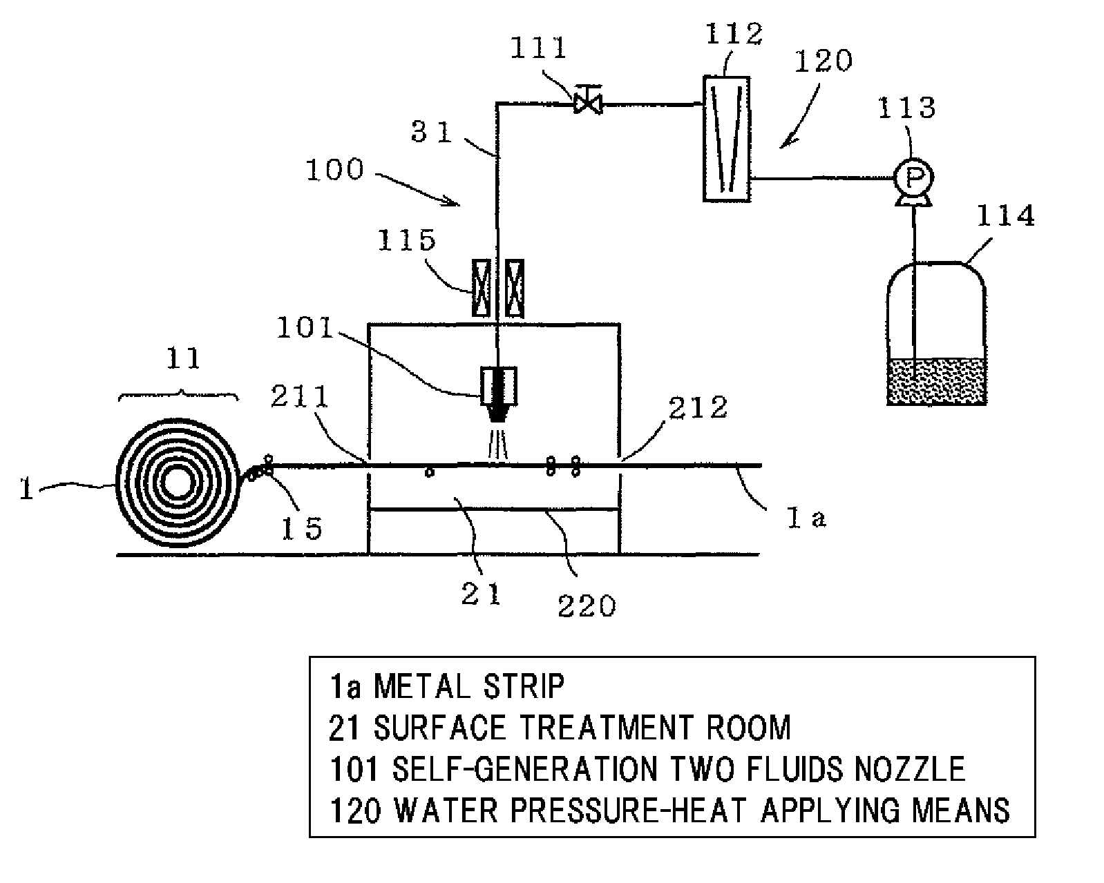
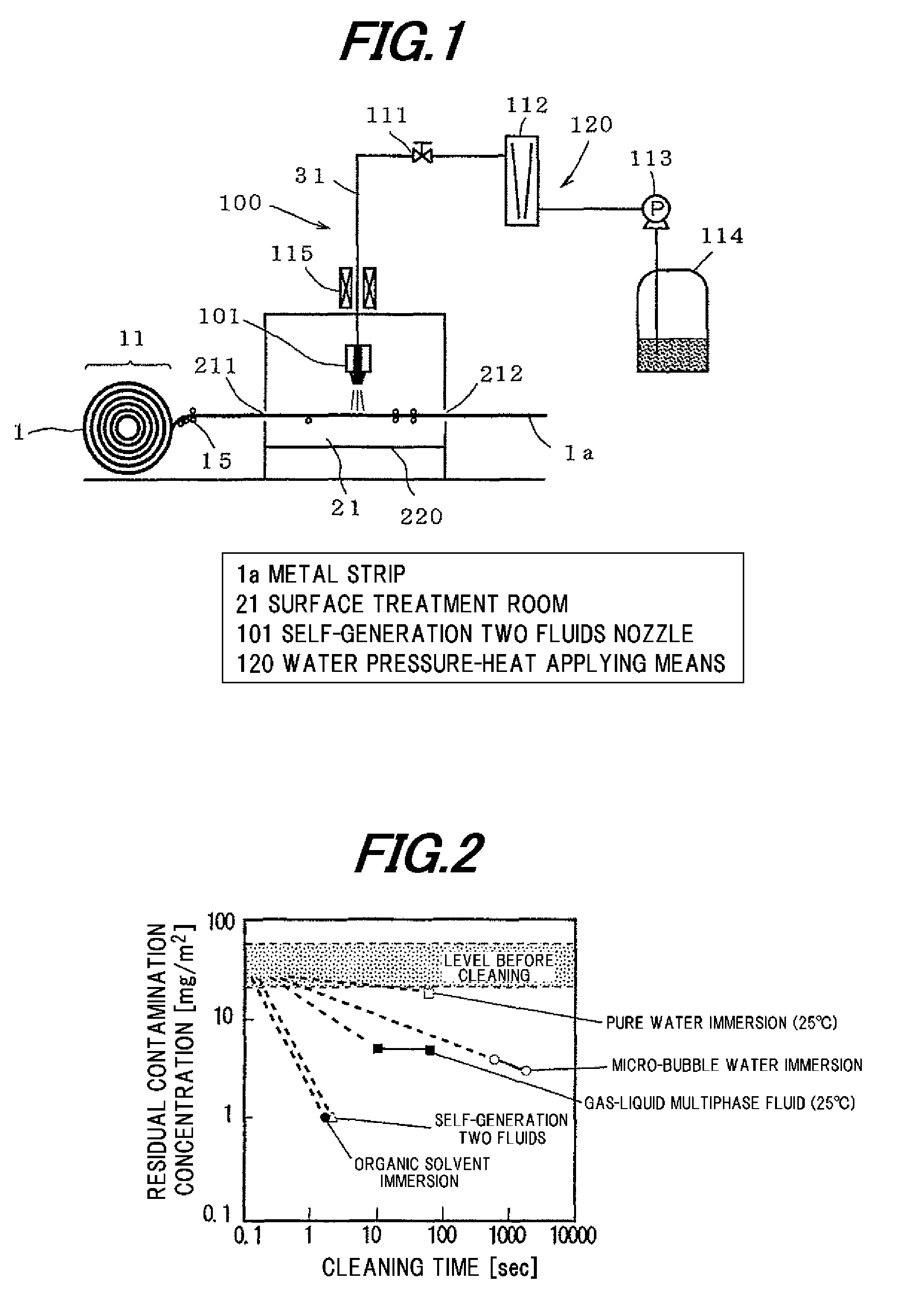
[0133]In FIG. 1, a copper strip after completion of a rolling process was used as the metal strip and a tank in which pure water is filled was used as the water tank, and removal of a rolling process lubricating oil on the surface of the copper strip was carried out.

[0134]The copper strip fed from the uncoiler 11 was introduced into the surface treatment room 21 from the inlet 211, after a cleaning treatment was applied thereto for a predetermined time, and was extracted from the outlet 212 to the outside of the surface treatment room 21. Water was fed from the water tank 114 while pressured by the pump 113 and reached the nozzle 101 via the flow meter 112 and the flow control valve 111. Heating was carried out by the heater 115 installed along the way of the piping 31.

[0135]As the self-generation two fluids nozzle 101 for discharging the self-generation two fluids, a nozzle manufactured by Spraying Systems Co., model number: HB-1 / 4-VV-SS-80-0050 was used. The spray angle was 80 deg...

example 2

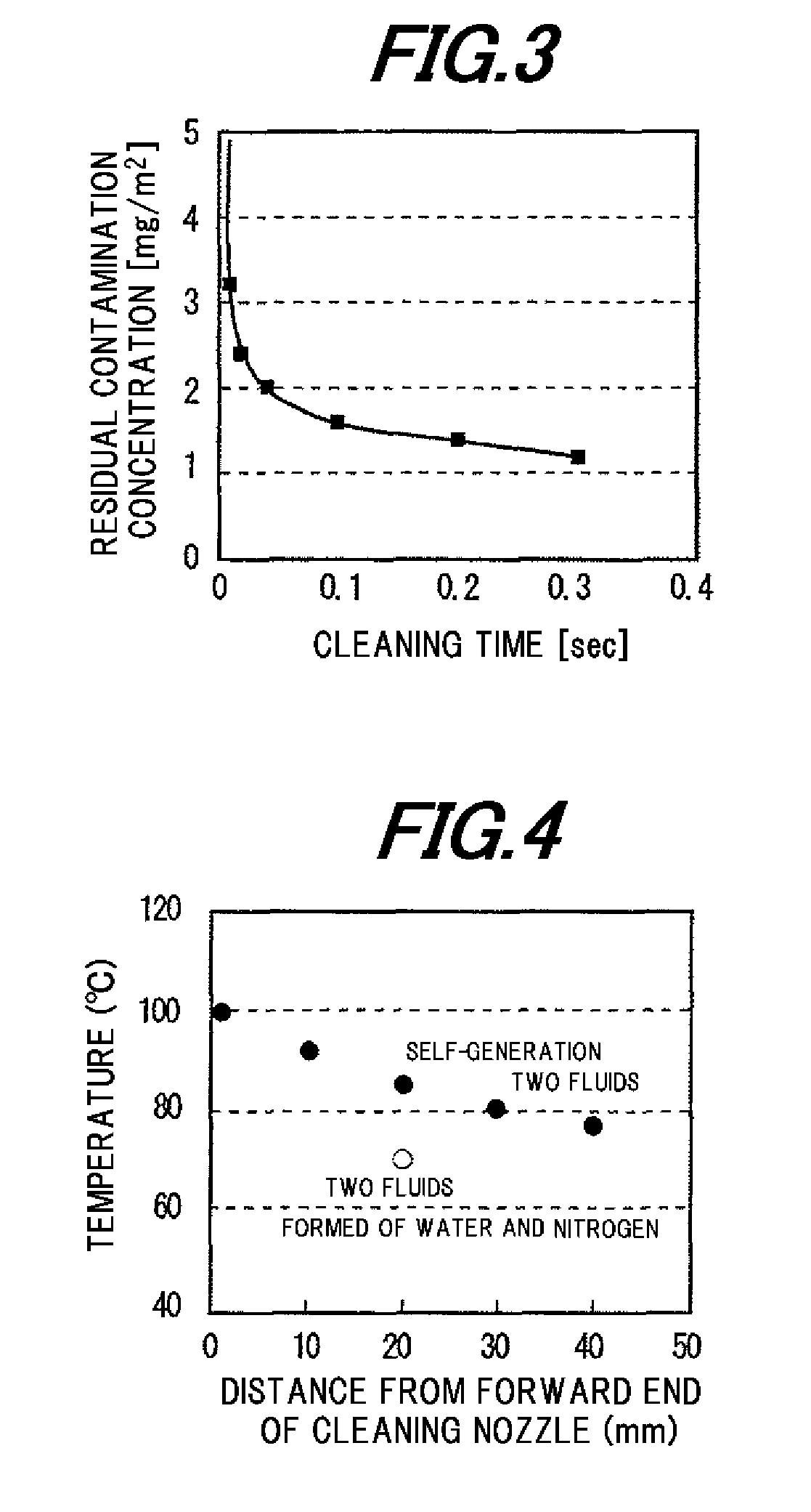
[0140]A cleaning was carried out in a shorter time by using the same spray nozzle as Example 1. The cleaning was carried out on the condition that a spray pattern located at a distance of 20 mm from the nozzle was a rectangular shape of 10×30 mm, and a width direction of the copper strip was corresponded to a long side of the spray pattern. The linear speed of the copper strip was set to 60 m / min. At this time, a time when the copper strip passes under the one spray is 0.01 second. A desired cleaning time was obtained by 1 to 30 nozzle(s) was (were) arranged in the surface treatment room 21, the linear speed was set to a constant value and the number of the nozzle was changed.

[0141]FIG. 3 shows a result from that the cleaning was carried out by using a copper strip having an oil concentration of almost 100 mg / m2, and the residual contamination concentration after cleaning was measured. It was confirmed that the copper strip of Example 2 became clean even if in a shorter time than Ex...

example 3

[0145]A generation of the self-generation two fluids and a cleaning treatment were carried out by using the surface treatment device explained in FIG. 5.

[0146]Namely, the surface treatment device shown in FIG. 5 is similar to the surface treatment device shown in FIG. 1, but a liquid is fed under pressure by a gas pressurizing instead of using a pump. In addition, heaters are installed in both locations along the way of the piping and at the water tank.

[0147]Here, the self-generation two fluids were generated by two systems respectively.

[0148]In a system A as one system, a temperature was constantly retained to 105 degrees C., and a pressure was adjusted by a pressure of the gas used for the feeding under pressure. Since a vapor pressure of water at the temperature is 0.15 MPa, in case that a pressure equal or higher than the pressure was needed, pressurizing due to introducing a gas was carried out.

[0149]In a system B as another system, heating was carried out so that the vapor pre...


PUM

PropertyMeasurementUnit
Pressureaaaaaaaaaa
Angleaaaaaaaaaa
Angleaaaaaaaaaa

Abstract

A surface treatment method of a metal member according to an embodiment of the invention includes removing an oily substance on the metal member by using gas-liquid two fluids that are obtained by boiling heated and pressured water under ordinary pressure. A surface treatment device of a metal member for removing an oily substance on the metal member includes self-generation two fluids production means for producing gas-liquid two fluids by boiling heated and pressured water under ordinary pressure, and a surface treatment room carrying out a surface treatment by bringing the self-generation two fluids into contact with the metal member.

Description

[0001]The present application is based on Japanese patent application Nos. 2009-199991, 2010-031473 and 2010-110711 filed on Aug. 31, 2009, Feb. 16, 2010 and May 13, 2010, respectively, the entire contents of which are incorporated herein by reference.BACKGROUND OF THE INVENTION[0002]1. Field of the Invention[0003]This invention relates to a surface treatment method of a metal member including copper and a surface treatment device, and in particular, this invention relates to a surface treatment method of a metal member and a surface treatment device at the time of manufacturing the metal member such as a strip material, a wire material.[0004]In addition, this invention relates to a cleaning technique capable of enhancing a cleaning degree of surfaces of various solid substances, for example, from a metal to which a mechanical processing is applied, such as a rolled steel plate, a cutting-worked product, to a semiconductor wafer to which a dry etching process is applied, and in part...

Claims


Application Information

Patent Timeline
IPC IPC(8): B08B3/00
CPCC23G5/00B08B3/022
Inventor SAEKI, TOMONORIANDO, YOSHIYUKI
Owner HITACHI CABLE
Why Eureka
Try Eureka