Short-tube drawing parts co-direction full row feeding device

A feeding device and a short tube technology, which is applied in the field of the same-direction alignment feeding device for short-tube stretched parts, can solve problems such as the difficulty of alignment in the same direction, and achieve the effect of precise feeding

Active Publication Date: 2022-04-05
SHANDONG HUAMIN STEEL BALL
View PDF0 Cites 0 Cited by
  • Summary
  • Abstract
  • Description
  • Claims
  • Application Information

AI Technical Summary

Problems solved by technology

It solves the technical problem of difficulty in alignment in the same direction for automatic stamping and continuous feeding of thin-wall stretched short tube parts for multiple stretches, and realizes precise feeding of automatic stamping lines

Method used


Image

  • Short-tube drawing parts co-direction full row feeding device
  • Short-tube drawing parts co-direction full row feeding device
  • Short-tube drawing parts co-direction full row feeding device

Examples


Embodiment Construction

[0026] The features and principles of the present invention will be described in detail below in conjunction with the accompanying drawings, and the examples given are only used to explain the present invention, not to limit the protection scope of the present invention.

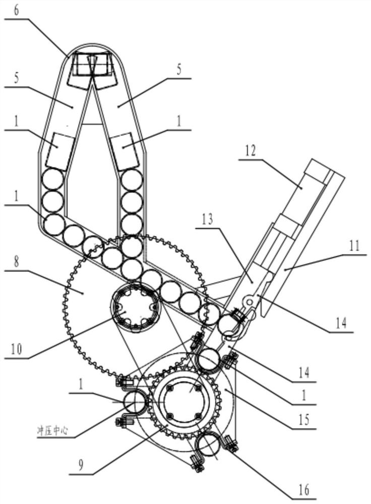
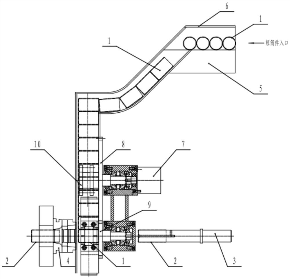
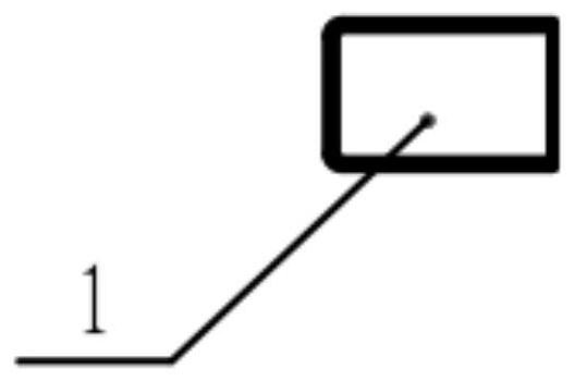
[0027] attached figure 2 The upper right end is the part to be stretched 1 ( image 3 )Entrance. The parts 1 to be stretched are transported to the branch guide groove 5 by a traditional alignment machine, and the parts 1 to be stretched are arranged horizontally. The part 1 to be stretched has a bottom end and a bottom end, and there is no direction in the distribution guide groove.

[0028] Stretching member 1 passes through the inverted "V" shaped ridge at the bottom of the branch guide groove 5 (as attached figure 2 Shown), there is the part 1 to be stretched with the bottom facing forward because the center of gravity is forward, when the center of gravity exceeds the inverted "V" shape edge of the...


PUM


Abstract

The invention discloses a feeding device in the same direction for short-tube stretching parts, which includes a branch guide groove, the top of the branch guide groove is a limit arc, and the bottom of the branch guide groove is an inverted V-shaped edge. The slots line up in the same direction and move down along the chute connected with the top and the branch guide trough. The end of the chute is close to the automatic claw finger, which is connected with the cylinder. The workpiece to be stretched enters the rotary feeder through the automatic finger. The two sides of the rotary feeder are respectively equipped with a die and a movable punch. It solves the technical problem that the thin-wall stretched short tube is stretched for multiple times, automatic stamping, continuous feeding, and alignment in the same direction, and realizes accurate feeding of the automatic stamping line.

Description

technical field [0001] The invention relates to the technical field of mechanical automation equipment, in particular to a co-direction alignment feeding device for short-tube stretched parts. Background technique [0002] Similar traditional alignment technologies mainly include the following: [0003] 1. When the light and bottomed cylindrical parts are arranged in columns along the direction of the track by using air resistance, the uphill and downhill barrier boards are set on the track, and the workpieces are sprayed with air when they are about to go downhill. When workpieces pass through here, the alignment is realized by utilizing the difference in air resistance of the end faces. [0004] 2. The protruding length of the cylindrical parts with a heavy bottom and a long length at the end of the track varies depending on whether the bottom is in front or the bottom is behind, so as to realize the alignment. It is suitable for cylindrical parts with large weight diffe...

Claims


Application Information

Patent Timeline
Patent Type & Authority Patents(China)
IPC IPC(8): B21D43/00B21D22/20B65G47/82
CPCB21D43/00B21D22/20B65G47/82
Inventor 侯宇岷王克川臧华勋
Owner SHANDONG HUAMIN STEEL BALL
Why Eureka
Try Eureka