Scratch-free discharge device based on tapered roller rolling properties

A technology of tapered rollers and properties, applied in the field of non-scratch discharge devices, can solve problems such as troublesome, easy to flip rollers, and high skill requirements for operators

Active Publication Date: 2021-04-23
YANTAI GOYOU PRECISION BEARING
View PDF0 Cites 0 Cited by
  • Summary
  • Abstract
  • Description
  • Claims
  • Application Information

AI Technical Summary

Problems solved by technology

[0003] First, because the tapered roller is pushed forward by clamping the working surface of the tapered roller with two rollers, the working surface of the tapered roller will be scratched to a certain extent, and the problem of scratching has always been a quality problem that users are very concerned about. , in order to reduce scratches, the rolling rod needs to be disassembled frequently for grinding, which is very troublesome;
[0004] Second, the rollers are easily loaded into the bearings upside down when the ends of the rollers are dropped, which is a very serious quality problem
For rollers with small diameters, it is very easy to flip the rollers. After assembly, it is found that when the rollers are flipped, the cage must be removed and scrapped, resulting in great waste;
[0005] Third, when changing the model, it is necessary to adjust the position of the feeding roller to ensure that the tapered roller automatically falls into the material receiving port of the material receiving rod when it is sent to the end. It is difficult to adjust the position of the material receiving port. It requires higher skills for operators, but at present, the turnover of personnel is high, and the cost of changing models is relatively high.

Method used


Image

  • Scratch-free discharge device based on tapered roller rolling properties
  • Scratch-free discharge device based on tapered roller rolling properties
  • Scratch-free discharge device based on tapered roller rolling properties

Examples


Embodiment Construction

[0030] The implementation mode of the present invention is illustrated by specific specific examples below, and those who are familiar with this technology can easily understand other advantages and effects of the present invention from the contents disclosed in this description. Obviously, the described embodiments are a part of the present invention. , but not all examples. Based on the embodiments of the present invention, all other embodiments obtained by persons of ordinary skill in the art without making creative efforts belong to the protection scope of the present invention.

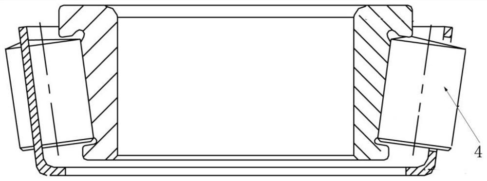
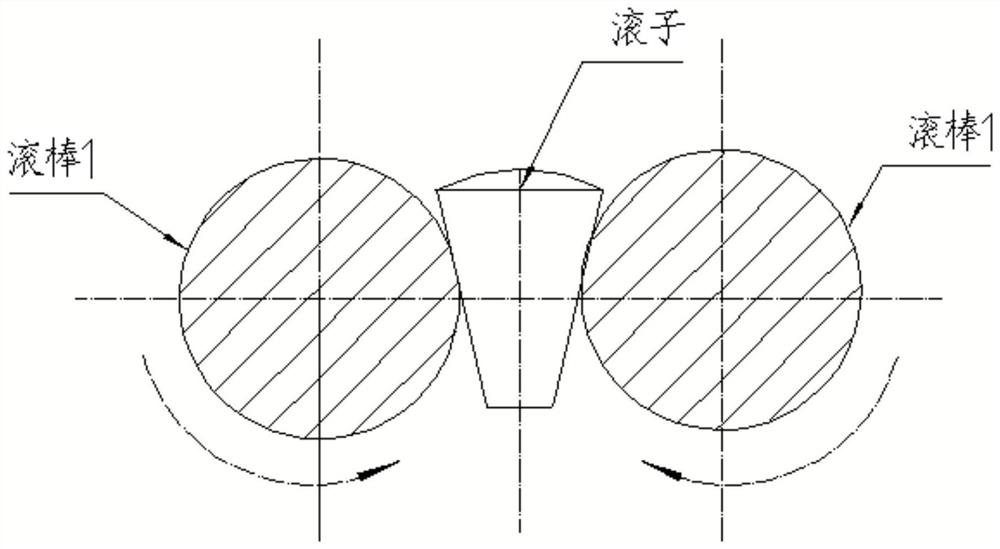
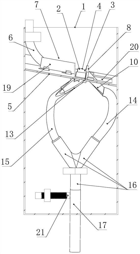
[0031] Compared figure 1 and figure 2 , see image 3 and Figure 4 , providing a non-scratch discharge device based on the rolling properties of tapered rollers, including a box body 1 for discharging tapered rollers 4 with a large-diameter end 2 and a small-diameter end 3, and the box body 1 is internally connected There is an inclined material distributing table 5; the top of the material ...


PUM


Abstract

A non-scratch discharge device based on the rolling properties of tapered rollers. There is an inclined material distribution table connected inside the box; there is a roller discharge pipe above the material distribution table, and a roller material channel is also provided at the upper end of the material distribution table; A blanking baffle is provided on one side of the sub-feeder, and the blanking baffle is formed with a first blanking hole, and the first blanking hole is connected with a first material guide head; the end of the blanking baffle is connected with a limit baffle, The distributing table is provided with a second feeding hole on one side of the limit baffle, and the second feeding hole is connected with the second material guide head; The second material guide head is connected with the second material receiving pipe under the distribution platform; the ends of the first material receiving pipe and the second material receiving pipe are connected with a Y-shaped tee, and one end of the Y-shaped tee is connected with an outlet Feed tube. This technical solution can quickly arrange the tapered rollers with low energy consumption and no scratches. The tapered rollers can be automatically arranged with the small end facing down under no power drive, which can avoid the phenomenon of roller inversion and ensure the product quality of the bearing.

Description

technical field [0001] The invention relates to the technical field of bearing detection, in particular to a non-scratch discharge device based on the rolling properties of tapered rollers. Background technique [0002] When the tapered roller is assembled, the small end of the tapered roller needs to face down, and it will automatically fall into the cage through the pipe to realize automatic assembly. see figure 1 , in order to achieve this function, it is currently widely used that the roller falls between the two rollers, and the roller naturally stands between the two rods with the big end facing upwards, and the rollers are pushed forward by the rotation of the two rollers. Falls into the splicing rod when the end of the roller is reached, see figure 2 , this method has three drawbacks: [0003] First, because the tapered roller is pushed forward by clamping the working surface of the tapered roller with two rollers, the working surface of the tapered roller will b...

Claims


Application Information

Patent Timeline
Patent Type & Authority Patents(China)
IPC IPC(8): B65G47/24B65G47/88F16C43/06
CPCB65G47/24B65G47/88F16C43/065
Inventor 田俊英商锦海徐涛
Owner YANTAI GOYOU PRECISION BEARING
Why Eureka
Try Eureka