Quick-connection type center rod pulling structure and split type fidelity corer pressure experiment structure

A quick-connect and plug-in structure technology, which is applied in the direction of extracting the undisturbed core device, earthwork drilling and mining, etc., can solve the problems of damage to the pressure-holding experimental cabin and untrue experimental results, so as to prevent damage, reliable performance, and improve work efficiency Effect

Pending Publication Date: 2020-08-25
SICHUAN UNIV
View PDF0 Cites 2 Cited by
  • Summary
  • Abstract
  • Description
  • Claims
  • Application Information

AI Technical Summary

Problems solved by technology

[0006] In addition, the existing pressure-holding test chamber is connected to the hydraulic pipeline by drilling holes in the wall of the

Method used


Image

  • Quick-connection type center rod pulling structure and split type fidelity corer pressure experiment structure
  • Quick-connection type center rod pulling structure and split type fidelity corer pressure experiment structure
  • Quick-connection type center rod pulling structure and split type fidelity corer pressure experiment structure

Examples


specific Embodiment approach 1

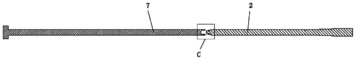
[0057] like Figure 1-6 As shown, the quick-connect central rod pulling structure disclosed in the present invention includes a pull rod 7, a central rod 2 and a quick plug-in structure. The quick plug structure includes a plug part 24 , a socket part 71 adapted to the plug part 24 and at least two spring buckles 9 . The plug part 24 and the socket part 71 are respectively connected with one of the pull rod 7 and the central rod 2 . Connected here means that two separate parts are connected together or manufactured in one piece. Link to each other with plug part 24 and central rod 2, jack part 71 is connected with pull rod 7 as example, plug part 24 can be manufactured integrally with central rod 2, and plug part 24 and central rod 2 also can be two independent parts, connect then to form A whole. Certainly, the plug part 24 can also be connected with the pull rod 7 , and the socket part 71 is connected with the central rod 2 .

[0058] The plug part 24 and the socket part...

specific Embodiment approach 2

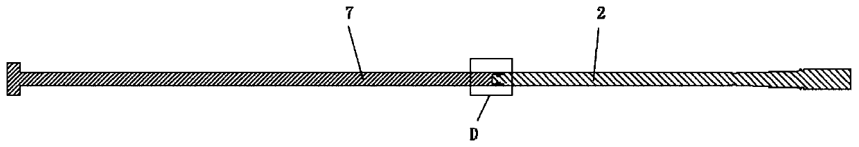
[0069] The difference between this embodiment and Embodiment 1 is that: Figure 5 As shown, in this embodiment, the plug portion 24 is integrally manufactured with the pull rod 7 , and the socket portion 71 is integrally manufactured with the central rod 2 of the pull rod 7 . The principle of this embodiment is the same as that of Embodiment 1, and will not be repeated here.

specific Embodiment approach 3

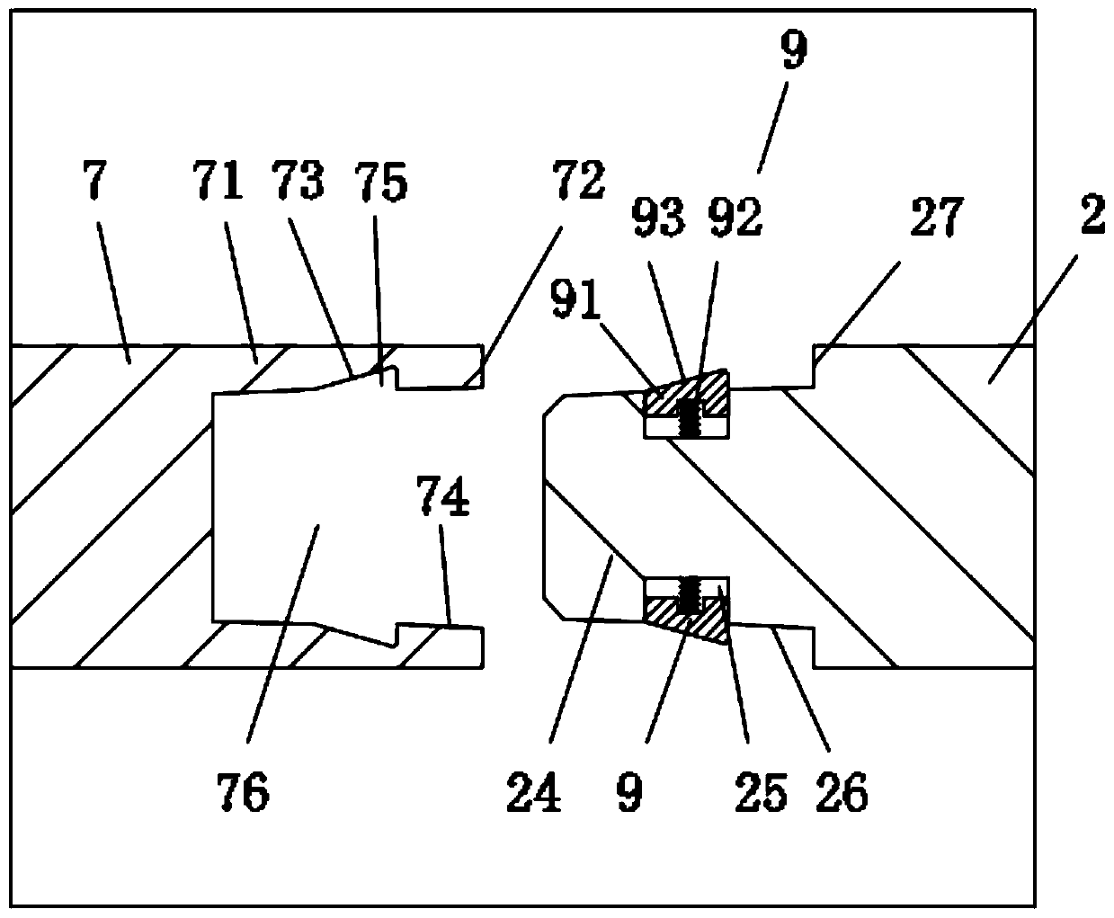
[0071] The difference between this embodiment mode and embodiment mode 1 or embodiment 2 is that: Image 6 As shown, in this embodiment, the spring buckle 9 is installed on the socket portion 71 . The spring buckle 9 includes a block 91 and a radially arranged spring 92 . The jack portion 71 is provided with a jack 76, the wall 74 of the jack 76 has a groove 25 for the block 91 to avoid, one end of the spring 92 is fixedly connected to the groove wall of the groove 25, and the other end of the spring 92 is fixedly connected to the block 91 Under the action of the spring 92, a part of the block 91 is located in the groove 25, and the other part of the block 91 protrudes from the wall 74 of the socket 76.

[0072] The outer side of the block 91 is a slope 93, so that when the plug part 24 is plugged into the socket part 71, the axial force of the plug part 24 acting on the slope 93 can generate a radial component force, and then push the block 91 to move radially to fully subm...


PUM


Abstract

The invention relates to a quick-connection type center rod pulling structure and a split type fidelity corer pressure experiment structure. The quick-connection type center rod pulling structure comprises a pull rod, a center rod and a quick inserting structure, wherein the quick inserting structure comprises a plug part, an inserting hole part and at least two spring buckles; the plug part and the inserting hole part are connected with one of the pull rod and the center rod respectively; and the plug part and the inserting hole part can be axially clamped and fixed through the spring buckles. Each spring buckle comprises a clamping block and a spring which is arranged in the radial direction; a groove for avoiding the clamping block is formed in an outer side wall of the plug part; an inclined plane is arranged at the outer side of the clamping block; when the plug part is inserted into the inserting hole part, the inserting hole part acts on the inclined plane and axial force can generate radial component force; and the clamping block is pushed to move in the radial direction until the clamping block is completely immersed into the groove. The quick-connection type center rod pulling structure is simple to operate and can realize rapid butt joint of the center rod and the pull rod, so that the working efficiency is conveniently improved; and a middle connection piece is usedfor connecting the upper end and the lower end of a pressure maintaining experiment cabin, so that a condition that holes are drilled in the pressure maintaining experiment cabin can be avoided and damages to the pressure maintaining experiment cabin are prevented.

Description

technical field [0001] The invention relates to the technical field of a coring device test system, in particular to a quick-connect central rod pulling structure and a split-type fidelity coring device pressure test structure. Background technique [0002] Mineral resources in the shallow part of the earth have been gradually exhausted, and marching into the deep part of the earth is an important direction for my country's scientific and technological innovation in the near future and in the future. The in-situ rock mechanical behavior of different deep host rock formations is the leading scientific and theoretical basis for deep drilling, deep resource development and utilization, and earth application science. [0003] The physical, mechanical, chemical and biological properties of deep rocks are closely related to their in-situ environmental conditions. The loss of in-situ environment during the coring process will lead to irreversible distortion of the physical, chemica...

Claims


Application Information

Patent Timeline
IPC IPC(8): E21B25/10E21B25/02
CPCE21B25/10E21B25/02Y02E30/30
Inventor 何志强谢和平高明忠吴年汉陈领李聪李佳南杨明庆余波胡云起
Owner SICHUAN UNIV
Why Eureka
Try Eureka