
Pulse width modulation type constant current source circuit

A pulse width modulation, constant current source technology, applied in the direction of adjusting electrical variables, control/regulating systems, instruments, etc., can solve the problems of complex process, expensive implementation, inability to achieve miniaturization and miniaturization, etc., and achieve high resolution. , the effect of high-precision voltage output

Active Publication Date: 2020-08-25
XIAN MICROELECTRONICS TECH INST
View PDF4 Cites 5 Cited by
  • Summary
  • Abstract
  • Description
  • Claims
  • Application Information

AI Technical Summary

Problems solved by technology

[0003] The purpose of the present invention is to provide a pulse width modulation type constant current source circuit, which solves the problems in the prior art that the implementation cost is relatively expensive, the process is relatively complicated, and miniaturization and miniaturization cannot be realized

Method used


Image

  • Pulse width modulation type constant current source circuit
  • Pulse width modulation type constant current source circuit
  • Pulse width modulation type constant current source circuit

Examples


Embodiment Construction

[0038]The present invention will be further described in detail below in conjunction with specific embodiments, which are explanations of the present invention rather than limitations.

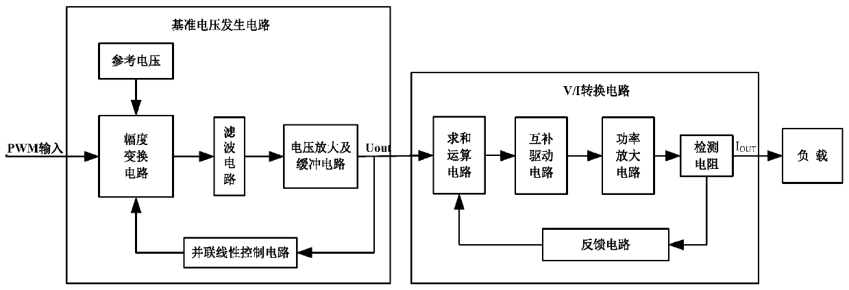
[0039] like figure 1 As shown, a pulse width modulation constant current source circuit disclosed in the present invention includes a reference voltage generation circuit and a V / I conversion circuit.

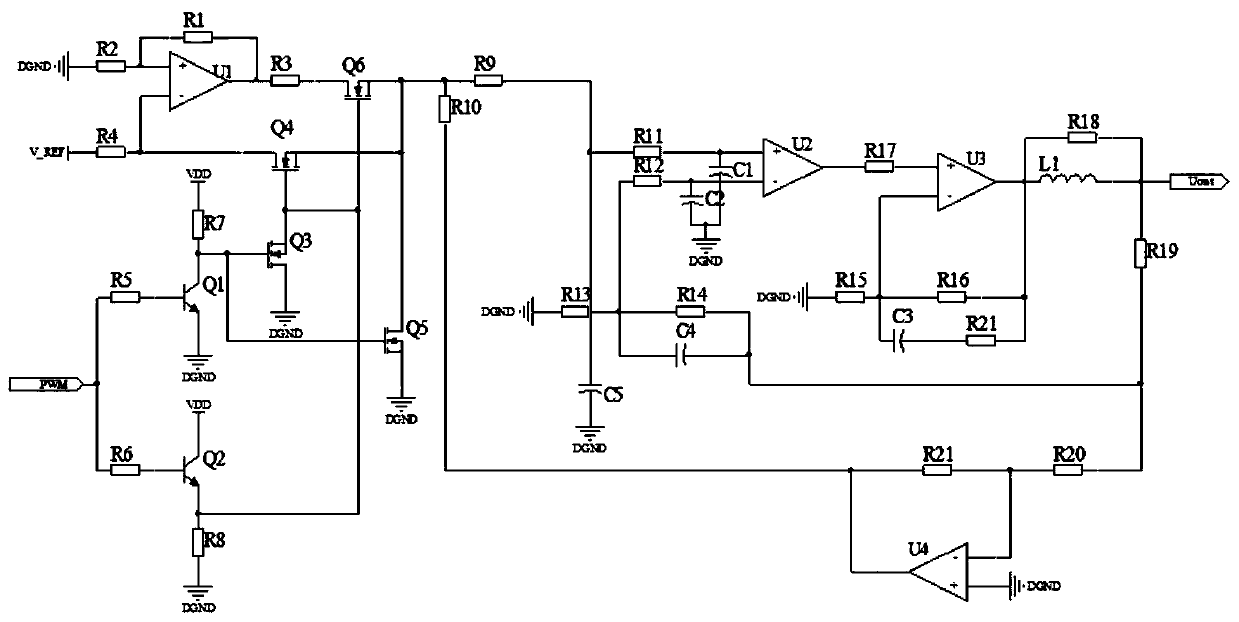
[0040] The reference voltage generation circuit includes an amplitude conversion circuit, a filter circuit, a voltage amplification buffer circuit and a parallel linear control circuit. The output terminal of the parallel linear control circuit is connected to the amplitude conversion circuit; the amplitude conversion circuit is used to input the PWM control signal and the reference voltage, the signal output by the amplitude conversion circuit is output as a DC voltage after the filter circuit, and the voltage amplification buffer circuit will output DC voltage amplification.

[0041] The am...


PUM


Abstract

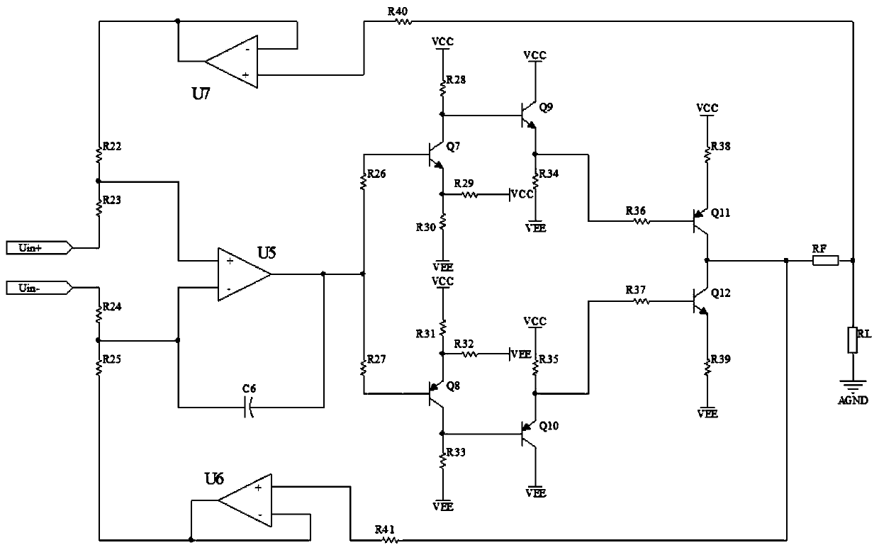
The invention discloses a pulse width modulation type constant current source circuit. The circuit comprises a reference voltage generation circuit and a V / I conversion circuit. The reference voltagegeneration circuit comprises an amplitude conversion circuit, a filter circuit, a voltage amplification buffer circuit and a parallel linear control circuit. The PWM control signal enables an output waveform to be switched between reference voltage VREF and 0V (ground) after passing through the amplitude conversion circuit, a signal output by the amplitude conversion circuit is output as direct current voltage after passing through the filter circuit, the direct current voltage is output after being amplified and isolated, and current driving is provided for output of the reference voltage generation circuit. The V / I conversion circuit comprises a summation operation circuit, a complementary driving circuit, a power amplification circuit, a detection resistor and a feedback loop, the V / I conversion circuit introduces current negative feedback into the amplification circuit, the detection resistor converts current into voltage, and feeds the voltage back to the summation operation circuit through the feedback loop, so that voltage-current conversion is realized. High-resolution and high-precision current output can be achieved by controlling PWM input signals.

Description

technical field [0001] The invention relates to the field of digital and analog circuits, in particular to a pulse width modulation type constant current source circuit. Background technique [0002] The constant current source is a common component in the control system. In addition to the common performance indicators such as output accuracy and current stability, which are gradually improved with the expansion of the application field, the demand for miniaturization and miniaturization is also increasing day by day. Commonly used program-controlled constant current source circuits generally use DA to generate a fixed voltage to achieve constant current output. To achieve higher output control accuracy, it is necessary to improve the DA output accuracy. In the implementation process, the controller needs to program and control the DA. The implementation cost is relatively expensive, the process is relatively complicated, and miniaturization and miniaturization cannot be ac...

Claims


Application Information

Patent Timeline
IPC IPC(8): G05F1/46G05F1/56G05F1/565G05F1/575G05F1/59
CPCG05F1/461G05F1/465G05F1/468G05F1/561G05F1/565G05F1/575G05F1/59
Inventor 秦凯亮饶张飞张邑炜刘瀚文
Owner XIAN MICROELECTRONICS TECH INST
Learn More