Push-pull entry marking frame for law teaching
A push-pull type and entry technology, which is applied in the field of push-pull law teaching entry display racks, can solve the problem of single function of the mixing device, and achieve the effect of easy carrying, convenient use, and stability
- Summary
- Abstract
- Description
- Claims
- Application Information
AI Technical Summary
Problems solved by technology
Method used
Image
Examples
Embodiment 1
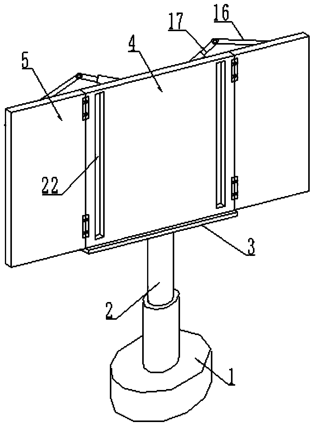
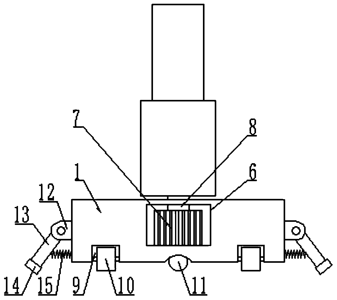
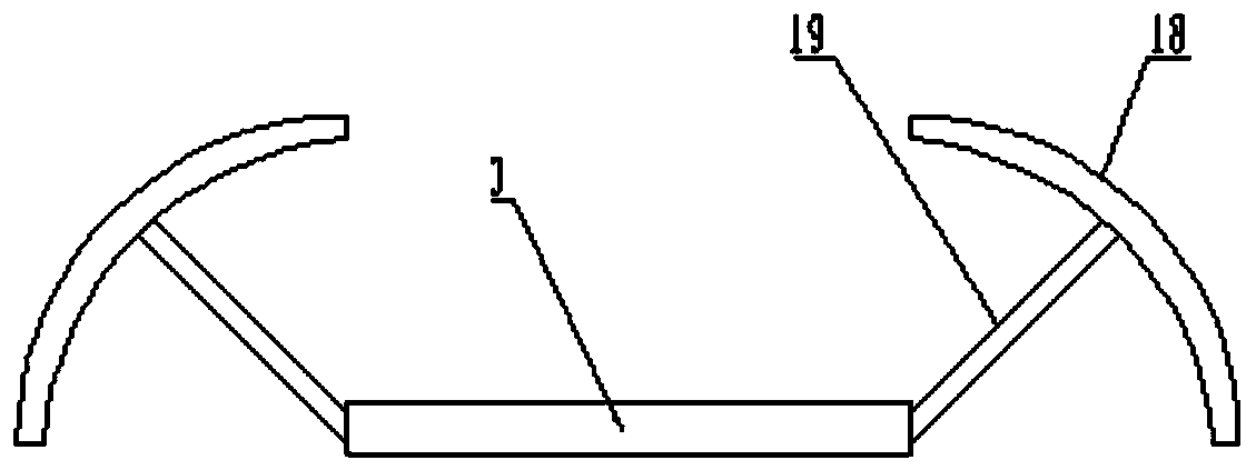
[0035] Such as figure 1 As shown, the embodiment of the present invention provides a push-pull type legal teaching item display rack, the item display rack includes an adjustable marking mechanism for placing items, and the adjustable marking mechanism is connected by a hydraulic telescopic oil cylinder 2 and a base 1 connection; the inside of the base 1 is provided with a rotating mechanism, and the rotating mechanism is fixedly connected with the hydraulic telescopic cylinder 2; the bottom of the base 1 is provided with a moving mechanism, and the side wall of the base 1 Equipped with a rotatable support mechanism.
[0036] The push-pull type law teaching item marking rack especially uses the adjustable marking mechanism to achieve the purpose of marking legal items, which can play an auxiliary role in law teaching, improve teaching efficiency, and help students understand and memorize. 2 and the rotating mechanism are connected with the base 1, avoiding the rigid and fixed...
Embodiment 2
[0049] Such as Figure 4~5 As shown, in yet another embodiment provided by the present invention, the main item indicator assembly includes a second motor 23 installed at the bottom of the bottom bracket 3, and the output end of the second motor 23 is connected to the second motor through a coupling. The rotating shaft 24 is driven and connected, and the second rotating shaft 24 is rotatably installed in the vertical groove 22 provided on the main board 4; the outer rings at both ends of the second rotating shaft 24 are provided with threads with opposite rotation directions, A slide block 25 is installed on the thread in a threaded connection, and a main entry card plate 27 is installed on the upper surface of the slide block 25; the opposite faces of the slide block 25 and the main entry card plate 27 are coated with magnetically different Coating 26.
[0050] The slider 25 can be used to install the main item clamping plate 27. By starting the second motor 23, the second r...
Embodiment 3
[0052] Such as Figure 4 with Image 6 As shown, in another embodiment provided by the present invention, the sub-entry indicates the assembly mounting plate 28 and the sub-entry clamping plate 31, the mounting plate 28 is uniformly set on the sub-plate 5, and the mounting plate 28 Both ends are provided with elastic bayonets 29, and the mounting plates 28 are connected by elastic chute 30, and the elastic chute 30 is connected between adjacent elastic bayonets 29; A clamping block 32 is fixed at the end, and the clamping block 32 is clamped on the elastic bayonet 29; the clamping plate 27 of the main item and the clamping plate 31 of the sub-item are provided with a clamping slot 33.
[0053] The sub-entry clamping plate 31 can be installed in the mounting plate 28 through the cooperation of the clamping block 32 and the elastic bayonet 29. When the position of the sub-item clamping plate 31 needs to be moved, the sub-item clamping plate 31 is pushed up and down, and the cla...
PUM
 Abstract
Description
Claims
Application Information
 - R&D
- Intellectual Property
- Life Sciences
- Materials
- Tech Scout
- Unparalleled Data Quality
- Higher Quality Content
- 60% Fewer Hallucinations
Browse by: Latest US Patents, China's latest patents, Technical Efficacy Thesaurus, Application Domain, Technology Topic, Popular Technical Reports.
© 2025 PatSnap. All rights reserved.Legal|Privacy policy|Modern Slavery Act Transparency Statement|Sitemap|About US| Contact US: help@patsnap.com


