Cable bundle sheath
A bundle sheath and cable bundle technology, which is applied in the field of semiconductor equipment, can solve the problems that the cable bundle cannot be distributed, local stress concentration cannot be avoided, and local stress is difficult to be evenly distributed, so as to ensure uniform dispersion and prevent breakage
- Summary
- Abstract
- Description
- Claims
- Application Information
AI Technical Summary
Problems solved by technology
Method used
Image

Examples
Embodiment Construction
[0022] In order to make the purpose, technical solution and advantages of the present invention clearer, the specific implementation manners of the present invention will be further described in detail below in conjunction with the accompanying drawings.
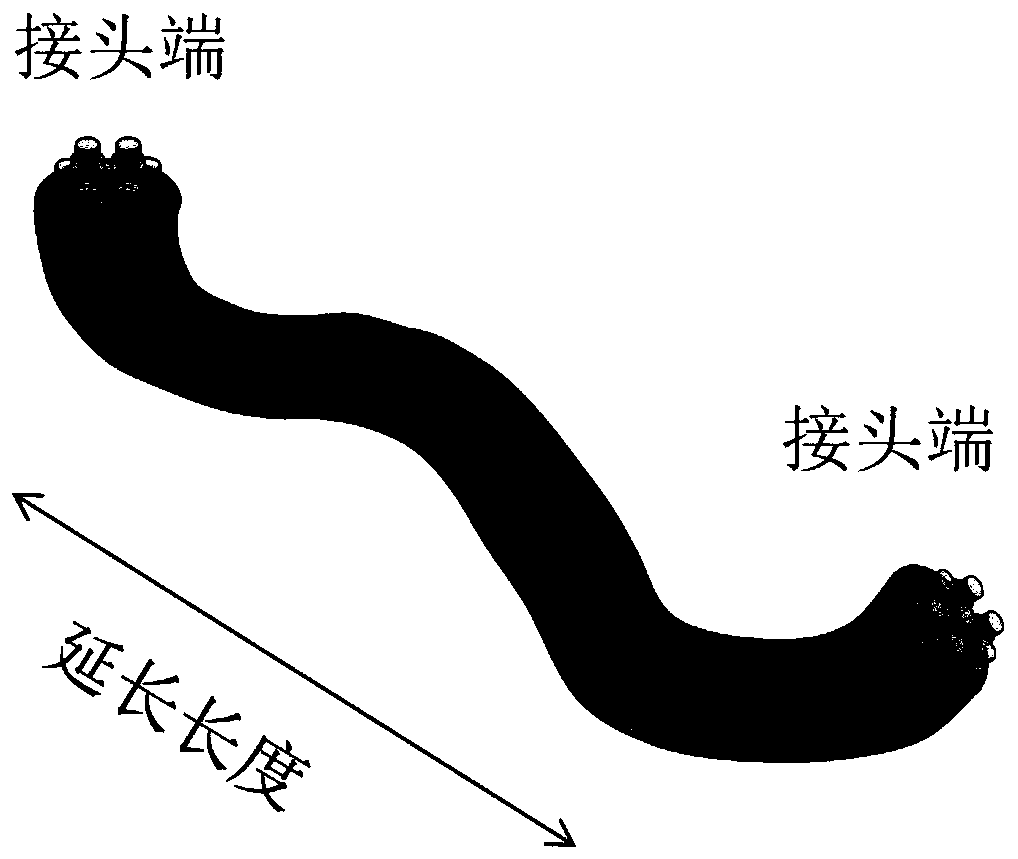
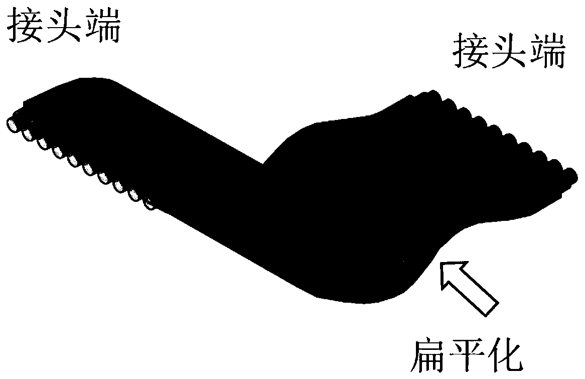
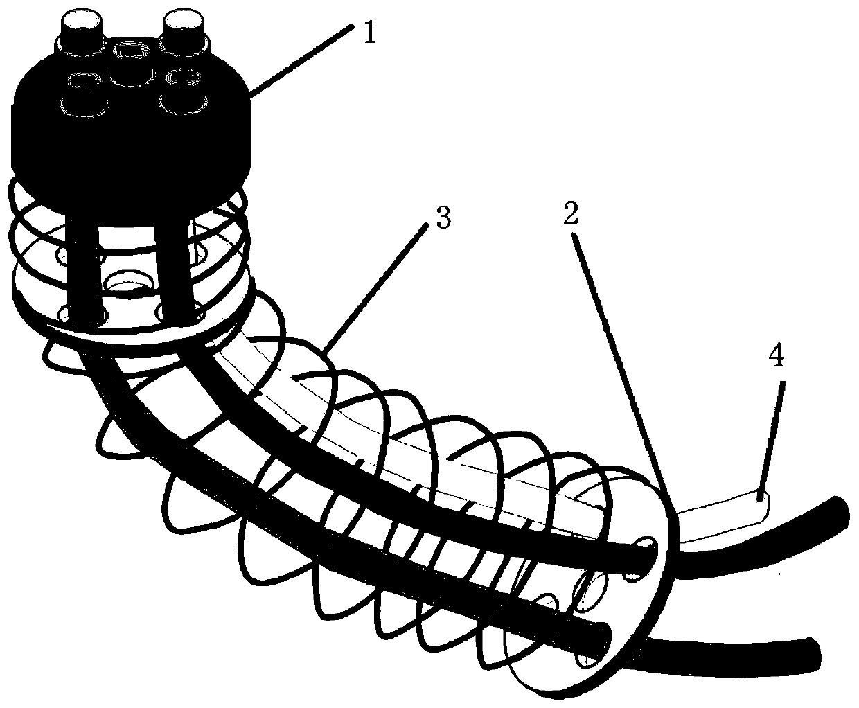
[0023] as attached image 3 And attached Figure 4 As shown, a cable harness sheath provided by the present invention includes a joint end 1 located at the end of the cable, M fixing plates 2 located in the middle of the cable harness, and a connecting spring 3 wound on the outside of the cable harness. There are preferably two terminals, which are respectively located at the two ends of the cable harness. In a special scenario, the connector at one end can also be omitted. The connector end contains N connector through holes, and the fixing plate includes N fixing through holes corresponding to the connector through holes; the connector end and the M fixing plates are connected by connecting springs, and at least one cable...
PUM
 Abstract
Description
Claims
Application Information
 - Generate Ideas
- Intellectual Property
- Life Sciences
- Materials
- Tech Scout
- Unparalleled Data Quality
- Higher Quality Content
- 60% Fewer Hallucinations
Browse by: Latest US Patents, China's latest patents, Technical Efficacy Thesaurus, Application Domain, Technology Topic, Popular Technical Reports.
© 2025 PatSnap. All rights reserved.Legal|Privacy policy|Modern Slavery Act Transparency Statement|Sitemap|About US| Contact US: help@patsnap.com