Steam waste heat recycling system for autoclaved aerated concrete blocks

A concrete block and steam waste heat technology, applied in the field of autoclave, can solve the problems of high temperature tensile stress, steam heat loss, cracking of concrete block concrete structure, etc., and achieve the effect of uniform cooling and ensuring uniform dispersion

Active Publication Date: 2022-04-26
SHANTOU XIJIA BUILDING MATERIALS
0 Cites 0 Cited by

AI-Extracted Technical Summary

Problems solved by technology

[0003] The autoclave uses steam as the heat source, but actually only the latent heat of the steam is used. The saturated condensate formed by steam condensation contains a lot of unused heat. Conventional steam The autoclave directly empties the autoclave body after curing, resulting in the heat loss of the steam. Therefore, in order to save heat, the autoclave ne...

Method used

And described rotary disk 401 is in the process of rotating, and the rotation angle of described air guide port 403 relative to air guide groove 304 is positively correlated with the rotation angle of rotary disk 401, and the rotation angle of described rotary disk 401 and moving sleeve The sliding distance of the barrel 301 is linearly related, so by controlling the rotation angle of the driving screw 607, the sliding distance on one side of the sliding member 601 can be controlled, thereby controlling the sliding distance of the moving sleeve 301, so that the air guide port 403 is opposite to the air guide groove. The inclination angle of 304 is controllable, which is convenient for precise control of the discharge of waste heat steam, and through several synchronously moving exhaust components 4, the discharge ...

Abstract

The invention discloses an autoclaved aerated concrete block steam waste heat recycling system, and belongs to the technical field of autoclaves, the autoclaved aerated concrete block steam waste heat recycling system comprises a main kettle body, a lining sleeve and a movable sleeve, the lining sleeve is fixedly assembled on the inner wall of the main kettle body, the movable sleeve is slidably assembled between the main kettle body and the lining sleeve, a gas guide groove is distributed in the movable sleeve, and the gas guide groove is communicated with the main kettle body. The movable sleeve is arranged between the main kettle body and the lining sleeve, a gas guide groove is formed in the movable sleeve, a gas exhaust component is arranged in the gas guide groove, the gas exhaust component comprises a plurality of rotary discs, gas guide openings are formed in the rotary discs and used for quantitatively outputting waste heat steam in the main kettle body, and the driving mechanism is used for driving the movable sleeve to directionally slide. The movable sleeve can be circularly driven to move through the driving mechanism in the cooling stage, so that waste heat steam in the main kettle body is quantitatively conveyed out of the kettle body through the exhaust component, uniform cooling of the kettle body is realized, the residual waste heat steam in the kettle body can circularly flow, and uniform dispersion of heat is ensured.

Application Domain

Technology Topic

Process engineeringAutoclaved aerated concrete +6

Image

  • Steam waste heat recycling system for autoclaved aerated concrete blocks
  • Steam waste heat recycling system for autoclaved aerated concrete blocks
  • Steam waste heat recycling system for autoclaved aerated concrete blocks

Examples

  • Experimental program(1)

Example Embodiment

[0039] To more clearly illustrate the structural features and efficacy of the present invention, the present invention is described in detail below in conjunction with the accompanying drawings and specific embodiments.
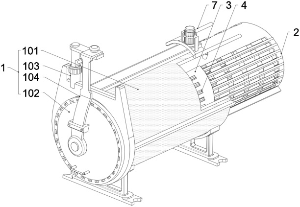
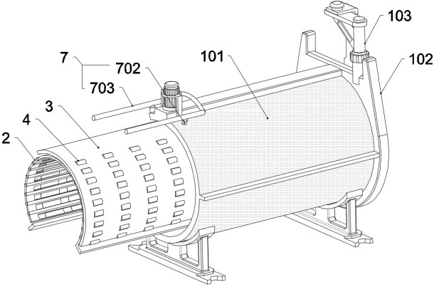
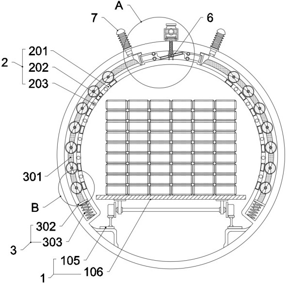
[0040] See Figure 1-Figure 6 , one embodiment of the present invention in an autoclaved aerated concrete block steam waste heat recovery system, comprising a kettle body member 1, the kettle body member 1 comprising the main kettle body 101 and the kettle cover 102, the waste heat recovery system further comprises: lining wall assembly 2, the lining wall assembly 2 comprises an inner liner sleeve 201 and an intake tank 202, the liner sleeve 201 is fixed to be assembled on the inner wall of the main kettle body 101, the upper cloth thereof is provided with several intake tanks 202, The air intake tank 202 array is laid on the liner sleeve 201; sleeve mechanism 3, the sleeve mechanism 3 comprises two sets of mobile sleeve 301, two sets of mobile sleeve 301 mirror image is laid on both sides of the inner wall of the main kettle body 101, and the sliding assembly is between the main kettle body 101 and the liner sleeve 201, the mobile sleeve 301 on the array cloth is provided with several air conduction grooves 304, the air conduction tank 304 and the intake tank 202 matching setting, and the mobile sleeve 301 is equipped with a seal 302 at one end, The seal 302 is assembled between the main kettle body 101 and the liner sleeve 201 by elastic sliding 303, the mobile sleeve 301 is equipped with an offset 307 at the other end, the contact 307 slide is laid between the main kettle body 101 and the liner sleeve 201, the mobile sleeve 301 and the main kettle body 101 is provided with an exhaust chamber 501, the mobile sleeve 301 and the inner liner sleeve 201 is provided with an intake chamber 502; The exhaust member 4 includes a plurality of rotary discs 401, the rotary disc 401 rotation is assembled in a number of gas conductive baths 304, and the air conduction tank 304 sliding seal is connected, the rotary disc 401 is opened with two sets of air vents 403, the two sets of air guide ports 403 are connected, for the process of following the rotation of the mobile sleeve 301 the waste heat steam inside the main kettle body 101 is quantitatively transported to the side of the exhaust chamber 501; The drive mechanism 6 is disposed between the two sides of the contact member 307, for moving the sleeve 301 by means of the contact member 307 to slide between the main kettle body 101 and the liner sleeve 201, the drive mechanism 6 includes two sets of slides 601 and a chute frame 603, a drive block 604 and a drive screw 607, the two sets of slides 601 sliding arrangement between the main kettle body 101 and the inner sleeve 201 and by the sag rack 603 fixed to the connection, The chute frame 603 is sliding equipped with a drive block 604, the drive block 604 is connected to the pressure wheel 605 assembly, for moving the drive block 604 by the pressure wheel 605 to compress the chute frame 603, so that the chute frame 603 drives the sliding member 601 between the main kettle body 101 and the inner sleeve 201 directional sliding; and the air valve assembly 7, the gas valve assembly 7 is laid on the main kettle body 101 and connected to the exhaust chamber 501, For discharging the waste heat steam in the exhaust chamber 501 to the outside of the main kettle body 101.
[0041] In practical application, when the autoclaving maintenance of the block is carried out through the steam waste heat recovery and utilization system, the block to be maintained after the static stop stage is first sent to the inside of the main kettle body 101, and a high temperature and high pressure steam gas is introduced to the inside of the kettle body, and between the heating stage and the constant temperature stage, the control heating rate is between 10 ° C and 25 ° C, when the temperature reaches the constant temperature stage, the strength of the concrete block begins to grow rapidly, at this time the control temperature is between 80 ° C and 90 ° C, and ensures that 90% To 100% relative humidity, when the constant temperature phase is completed enters the cooling phase.
[0042] In the process of the cooling stage, because the concrete has hardened, if the cooling rate is too fast, the formation of a large temperature difference of the cooling gradient, will produce a large temperature tensile stress, resulting in cracks in the concrete surface, destroying its concrete structure, at this time in the cooling process, by driving the drive screw 607 deployed on the side of the main kettle body 101 rotation, can drive the drive block 604 on the side of the drive screw 607 between the main kettle body 101 and the liner sleeve 201 directional sliding, And since the drive block 604 slide is assembled in the chute frame 603, so in the process of movement can drive the chute frame 603 between the main kettle body 101 and the liner sleeve 201 to do directional sliding, so as to drive the sliding member 601 on both sides of the slider 601 synchronous sliding, when the sliding member 601 on the side of the chute frame 601 drives towards the side of the drive block 604 When sliding occurs, the slider 601 preferentially and the offset 307 occurs to be offset, And press the offset 307 slides between the main kettle body 101 and the liner sleeve 201, while driving the mobile sleeve 301 to move.
[0043] When the mobile sleeve 301 slides between the main kettle body 101 and the liner sleeve 201, the rotary disc 401 assembled inside the air supply tank 304 is connected to the wall of the liner sleeve 201 during movement, and drives the rotary disk 401 to rotate, when the air guide port 403 on the rotary disc 401 is rotated to the side of the gas guide 304 slot, because the inner sleeve 201 side is connected to the inner cavity of the main kettle body 101 through the air intake tank 202, And the intake chamber 502 is arranged between the lined sleeve 201 and the moving sleeve 301, so when the air conduction port at one end 403 rotates to the side of the intake chamber 502, the high-pressure waste heat vapor contained in the intake chamber 502 flows through the air guide port 403 under pressure and flows towards the side of the exhaust chamber 501, and fills the cavity side of the exhaust chamber 501 under pressure, when the sliding member 601 is reset during the reverse rotation of the driving screw 607, The mobile sleeve 301 reverse reset under the elastic force of one side seal 302 and the elastic member 303, at this time the rotary disc 401 in the moving sleeve 301 rotates in reverse, so that the air conduction port 403 on both sides is resealed, and when the mobile sleeve 301 is reset, the offset member 307 on the side of the mobile sleeve 301 slides to the side of the valve assembly 7, so that the valve assembly 7 is connected to the exhaust cavity body 501, under the pressure of high temperature steam, the gas passes through the gas valve assembly 7 to the outside of the kettle body , variable to the rest of the boost kettle, can also be transported to the flash tank for supersaturated fluid gas-liquid separation, and at this time located on both sides of the sliding member 601 two sets of mobile sleeves 301 in the sliding member 601 reciprocating motion process can achieve alternating waste heat steam output, and in the process of alternating output due to the air flow disturbance driven by exhaust can make the waste heat steam inside the kettle circulate flow, so that the heat in the waste heat vapor is evenly distributed on the block, to ensure stable cooling during the cooling process.
[0044] And the rotary disc 401 in the process of rotation, the air guide port 403 relative to the rotary angle of the air conduction tank 304 is positively correlated with the rotation angle of the rotary disc 401, and the rotation angle of the rotary disk 401 is linearly related to the sliding distance of the moving sleeve 301, so that by controlling the rotation angle of the driving screw 607 can control the sliding distance of the sliding member 601, thereby controlling the sliding distance of the moving sleeve 301, so that the tilt angle of the air guide 403 relative to the gas groove 304 can be controlled It is convenient for precise control of the discharge of waste heat steam, and through a number of synchronous movement of the exhaust member 4, the discharge of waste heat steam can be stable and controllable, so as to achieve stable exhaust in the cooling process.
[0045] In one case in the present embodiment, the multi-stage kettle body between the main kettle body 101 and the flange structure between the kettle cover 102 and the main kettle body 101 are processed by integral forging, and the integrity of the kettle body is determined by ultrasonic nondestructive testing, so that it complies with the national standard provisions of JB / T4730.3.
[0046] In one case in the present embodiment, the main kettle body 101 and the kettle cover 102 are equipped with a kettle door associated safety lock and a pressure detection table, which are common technical means in the reactor, and will not be described herein.
[0047] In one case of the present embodiment, the autoclave low-level thermal energy apparatus comprises a static stop chamber heating apparatus, a boiler water preheating apparatus and a curing pool and a heat exchanger and the like.
[0048] See Figure 1 and 2 , in a preferred embodiment of the invention, the kettle body member 1 further comprises: a rotary frame 103, the rotary frame 103 is laid on the side of the main kettle body 101, which is equipped with a loading bridge 104, the assembly bridge 104 is connected to the kettle cover 102 assembly; and a guide rail 105, the guide rail 105 is laid inside the main kettle body 101, which is equipped with a carrier 106, for actively carrying a concrete block to be maintained at positive pressure.
[0049] In practical application of the present embodiment, the kettle cover 102 is assembled on the main kettle body 101 by the rotary frame 103 and the loading bridge 104, in the present embodiment, the main kettle body 101 may be adopted through type kettle body, may also be used exhaust type kettle cover structure kettle body, herein is not specifically limited.
[0050] In one case in the present embodiment, the kettle body at the end of the cooling phase, the inside of the kettle body is pumped to a vacuum by a vacuum pump, after the temperature pressure of the block is stabilized, the air is introduced into the inside of the kettle body through the safety handle ball valve after opening the kettle door, and to ensure that the difference between the bath temperature and the outdoor temperature is not greater than 40 ° C.
[0051] See Figure 3 , in one preferred embodiment of the invention, the lining wall assembly 2 further comprises a hot water exchange pipe 203, the hot water exchange pipe 203 is arranged inside the liner sleeve 201 and spaced between the intake tank 202, along the main kettle body 101 in the direction of the kettle body.
[0052] In practice, the hot water exchange pipe 203 is deployed in the inner lining sleeve 201 of the kettle body, in the case where the pressure value inside the kettle body tends to the standard atmospheric pressure, under the condition that it is difficult to discharge the waste heat steam through the pressure effect, by continuously inputting the water to be preheated in the hot water exchange pipe 203 inside the kettle body, a rapid heat exchange inside the kettle body can be realized, and the heat exchange rate is related to the flow rate of the water valve.
[0053] See Figure 5 , in one preferred embodiment in the present embodiment, the sleeve mechanism 3 further comprises: a fixed column 305, the fixed column 305 fixedly laid in the air supply tank 304 and the gas conduction groove 304 coaxially arranged; the perforation 306, laid on the fixed column 305, and the opening direction of the fixed column 305 and the layout direction of the gas guide port 403 matching the setting, so that the rotary disc 401 rotates between the main kettle body 101 and the inner sleeve 201, The air vent 403 in the rotary disc 401 is channeled to the perforation 306, such that the waste heat steam on the side of the intake chamber 502 passes through the air vent 403 and the intake chamber 502 into the side of the exhaust chamber 501.
[0054] The exhaust member 4 further comprises: a toothed side groove 402, the toothed groove 402 is disposed on the side of the rotary disc 401 and towards the side of the inner liner sleeve 201, for turning the connection between the rotary disc 401 and the inner bushing sleeve 201;
[0055] In practical application, when the rotary disc 401 is connected to the inner liner sleeve 201 through the tooth edge groove 402, the rotary disc 401 follows the rotary disc 401 rotation during the rotation process, and when both sides of the air vent 403 are rotated to the side of the perforation 306, through the air vent 403 at the end of the air vent 404, so that the air vent 403 is connected through the air vent 404 and the perforation 306, And the air vent 403 is connected to the exhaust chamber 501 and the intake chamber 502, respectively, so as to achieve the communication of the exhaust chamber 501 and the intake chamber 502, and at this time, the deflection angle of the air vent 403 relative to the perforation 306 can be controlled by moving the sliding distance of the sleeve 301, thereby controlling the size of the gap between the vent 403 and the vent 306, which is convenient for controlling the displacement of waste heat steam.
[0056] See Figure 4 and 6 , in a preferred embodiment of the invention, the drive mechanism 6 further comprises: a sliding wheel 602, the sliding wheel 602 is assembled on the sliding member 601, connected with the main kettle body 101 and the lined sleeve 201 rolling; the resistance wheel 605, the resistance wheel 605 is laid on the drive block 604, and the chute frame 603 slides; the guide column 606, the guide column 606 is fixedly laid before the main kettle body 101 and the liner sleeve 201, for defining the direction of motion of the drive block 604 And the drive machine 608, the drive machine 608 is laid on the main kettle body 101 and connected with the drive screw 607 assembly, for driving the rotation of the drive screw 607.
[0057] In practical application, when the drive machine 608 can drive the drive screw 607 synchronous rotation during the process of rotation, since the drive block 604 is connected to the drive screw 607 assembly, and the drive block 604 is assembled between the main kettle body 101 and the lined sleeve 201 through the guide column 606 limit, so when the drive screw 607 drive block 604 slides on the guide column 606, by the pressure wheel 605 and the drive block 604 slide the guavage frame 603, Under the pressure action of the drive block 604 slides along the gap between the main kettle body 101 and the liner sleeve 201, and the sliding direction is related to the direction of rotation of the driving screw 607, when the chute frame 603 drives the slider 601 towards one side of the movement process, the mobile sleeve 301 can drive the side of the movement between the main kettle body 101 and the liner sleeve 201, and at this time the other side of the mobile sleeve 301 is in a stopped state, Thus realizing a single-sided mobile sleeve 301 drives its upper rotary disk 401 movement, and the waste heat steam in the kettle is exported to the exhaust chamber 501 for discharge.
[0058] In one case in the present embodiment, the drive 608 preferably uses a reducer to drive, can be driven by linear drive screw 607 rotation control drive block 604 sliding distance, so that the overall waste heat vapor displacement can be controlled, to ensure that the temperature in the cooling process in a set threshold of stable decline.
[0059] See Figure 2 and 4 , in a preferred embodiment of the invention, the gas valve assembly 7 comprises: a one-way valve port 701, the one-way valve port 701 is provided near the access 307 side, for limiting the flow direction of the residual heat steam in the exhaust cavity 501; The exhaust pipe 703 is used to output the waste heat steam inside the main kettle body 101 to a low thermal energy device.
[0060] In practical application, the check valve port 701 is laid out on the side of the adapter 307, when the adapter 307 slides under the impetus of the sliding member 601, the one-way valve port 701 can be blocked on one side, so that the waste heat steam enters the exhaust chamber 501, the gas is blocked through the one-way valve port 701 to the outside of the kettle body, to avoid the leakage of steam inside the kettle, and the steam pipes on both sides of the kettle body can be connected by the gas pipe 702 and the exhaust pipe 703, And the use of the check valve nozzle 701 of the unidirectional principle to prevent gas backflow between the lines.
[0061] The above embodiment of the present invention provides a vapor waste heat recovery system of autoclaved aerated concrete block, and by the inner liner sleeve 201 is laid out inside the main kettle body 101, and the mobile sleeve 301 is actively deployed between the main kettle body 101 and the inner liner sleeve 201, the mobile sleeve 301 on both sides of the main kettle body 101 can be driven by the drive mechanism 6 cycle during the cooling stage, so that the waste heat steam inside the main kettle body 101 is quantitatively transported to the outside of the kettle body by the exhaust member 4 on the mobile sleeve 301 , so as to achieve uniform cooling of the kettle body, and can drive the remaining waste heat steam in the kettle body to circulate, to ensure the uniform distribution of steam heat.
[0062] The foregoing is only a preferred embodiment of the present invention and is not intended to limit the present invention, and any modifications, equivalent substitutions and improvements made within the spirit and principles of the present invention shall be included within the scope of the present invention.

PUM

no PUM

Description & Claims & Application Information

We can also present the details of the Description, Claims and Application information to help users get a comprehensive understanding of the technical details of the patent, such as background art, summary of invention, brief description of drawings, description of embodiments, and other original content. On the other hand, users can also determine the specific scope of protection of the technology through the list of claims; as well as understand the changes in the life cycle of the technology with the presentation of the patent timeline. Login to view more.

Similar technology patents

Cooling device for automobile die

InactiveCN109434082AUniform coolingFlow is easy to controlEngineeringCold air
Owner:TIANJIN MOTOR DIES

Metal mold

Owner:HUNAN INSTITUTE OF ENGINEERING

Classification and recommendation of technical efficacy words

  • Uniform cooling
  • Ensure uniform dispersion

Steel plate manufacturing facility and manufacturing method

InactiveUS20120017660A1Little surface temperature deviationUniform coolingTensioning/braking arrangementsExtrusion cleaning devicesSteel platesEngineering
Owner:JFE STEEL CORP
Why Eureka
Try Eureka