Distribution network mechanical direct-current switch cabinet

A DC switch, mechanical technology, applied in the direction of pull-out switchgear, switchgear, switchgear components, etc., can solve the problems of cumbersome installation and later maintenance, complex structure, low safety and reliability, etc., and achieve reduction Overall loop inductance, simple structure, and easy access to the cabinet

Pending Publication Date: 2020-08-25
CHANGZHOU BORI ELECTRIC POWER AUTOMATION EQUIP +2
View PDF0 Cites 1 Cited by
  • Summary
  • Abstract
  • Description
  • Claims
  • Application Information

AI Technical Summary

Problems solved by technology

However, the existing load switchgear has a complex structure, cumbersome installation and later maintenance, and low safety and reliability.

Method used


Image

  • Distribution network mechanical direct-current switch cabinet
  • Distribution network mechanical direct-current switch cabinet
  • Distribution network mechanical direct-current switch cabinet

Examples


Embodiment Construction

[0019] In order to make the content of the present invention more clearly understood, the present invention will be further described in detail below based on specific embodiments and in conjunction with the accompanying drawings.

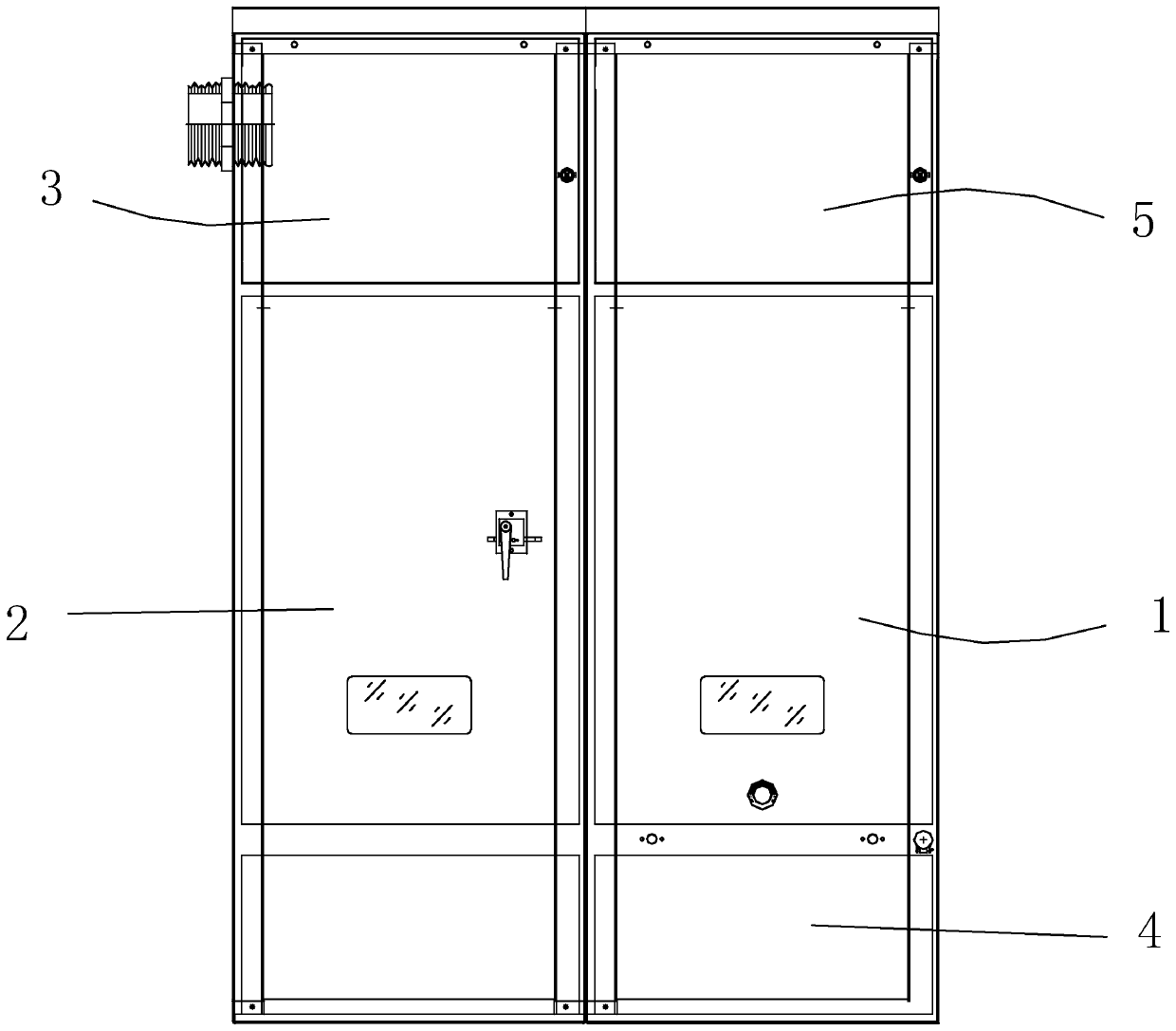
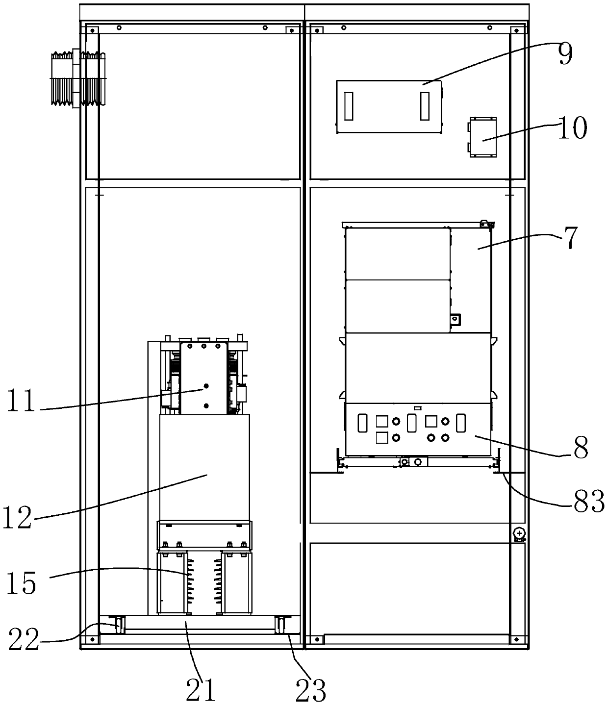
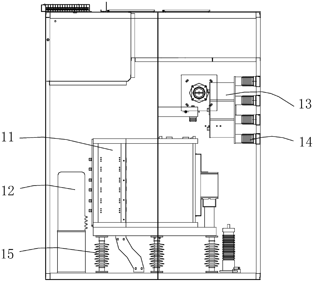
[0020] Such as Figure 1~6 As shown, a distribution network mechanical DC switchgear, the length, width and height of the cabinet in this embodiment are 1600mm*1800mm*2300mm, which includes a circuit breaker room 1, a valve room 2, a bus room 3, a cable room 4 and a control In the instrument room 5, all the compartments are metal-enclosed independent compartments. Through the position arrangement of the independent compartments, the direction of pressure release can effectively avoid operators and other equipment. The busbar room 3 and the control instrument room 5 are located in the upper part of the cabinet, the circuit breaker room 1 and the valve room 2 are located in the middle of the cabinet, the cable room 4 is located in the lower part of t...


PUM


Abstract

The invention discloses a mechanical direct-current switch cabinet of a distribution network. The circuit breaker comprises a circuit breaker chamber, a valve chamber, a bus chamber, a cable chamber and a control instrument chamber, the bus chamber and the control instrument chamber are positioned at the upper part of the cabinet body; the circuit breaker chamber and the valve chamber are locatedin the middle of the cabinet body, the cable chamber is located on the lower portion of the cabinet body, a power module for triggering loop energy supply and a control device are arranged in the control instrument chamber, a quick switch handcart and a contact box are arranged in the circuit breaker chamber, and a transfer branch, a lightning arrester and an energy supply transformer are arrangedin the valve chamber. The invention provides a distribution network mechanical direct-current switch cabinet which is compact in structure, reasonable in layout, convenient to assemble and maintain and safe and stable in operation.

Description

technical field [0001] The invention relates to a distribution network mechanical DC switch cabinet. Background technique [0002] At present, load switches are widely used in distribution network systems. As the key equipment in the medium and low voltage DC power distribution system, the ±10kV DC load switch has attracted more and more attention from the power industry, and related technologies are also making continuous progress. However, the existing load switchgear has a complex structure, cumbersome installation and later maintenance, and low safety and reliability. Contents of the invention [0003] The technical problem to be solved by the present invention is to overcome the deficiencies of the prior art and provide a distribution network mechanical DC switchgear with compact structure, reasonable layout, easy assembly and maintenance, and safe and stable operation. [0004] In order to solve the problems of the technologies described above, the technical soluti...

Claims


Application Information

Patent Timeline
Patent Type & Authority Applications(China)
IPC IPC(8): H02B11/167H02B11/26H02B11/02
CPCH02B11/02H02B11/167H02B11/26
Inventor 姚宁陈新王智勇吴中友杜道忠杨兵王文杰
Owner CHANGZHOU BORI ELECTRIC POWER AUTOMATION EQUIP
Why Eureka
Try Eureka