Implantable retinal electrical stimulator and its implant

An electric stimulator and implant technology, applied in the direction of electrodes, internal electrodes, head electrodes, etc., can solve the problems of easy compression of the vortex vein of the eyeball, long operation time, complications caused by compression of the vortex vein of the eyeball, etc.

Active Publication Date: 2021-02-19
INTELLIMICRO MEDICAL CO LTD
View PDF1 Cites 0 Cited by
  • Summary
  • Abstract
  • Description
  • Claims
  • Application Information

AI Technical Summary

Problems solved by technology

[0004] In related technologies, during the implantation operation, doctors usually need to open the conjunctiva around the eye at 360°, suspend all 4 medial ocular rectus muscles, and pass 4 suture hooks under the 4 rectus muscles, Moreover, it is required to set fixed sutures in each quadrant of the eye to complete the operation. This suture process is easy to compress the vortex vein of the eyeball, and postoperative complications are likely to be caused by the compression of the vortex vein of the eyeball. The operation process is cumbersome and the operation time is long, which increases the difficulty of implantation surgery

Method used


Image

  • Implantable retinal electrical stimulator and its implant
  • Implantable retinal electrical stimulator and its implant
  • Implantable retinal electrical stimulator and its implant

Examples


Embodiment Construction

[0037] Embodiments of the present invention are described in detail below, and the embodiments described with reference to the drawings are exemplary, and embodiments of the present invention are described in detail below.

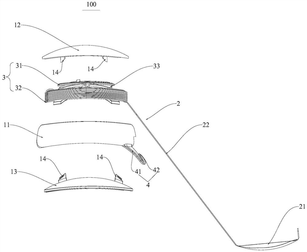
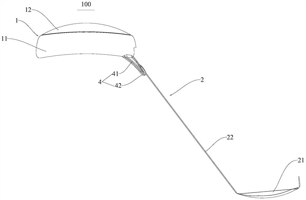
[0038] Refer below Figure 1-Figure 7 The implant body 100 of the implantable retinal electrical stimulator according to the embodiment of the first aspect of the present invention is described. The implant 100 according to the embodiment of the present invention may include: an annular housing 11 , a stimulation circuit assembly 2 and a suture hook 4 .

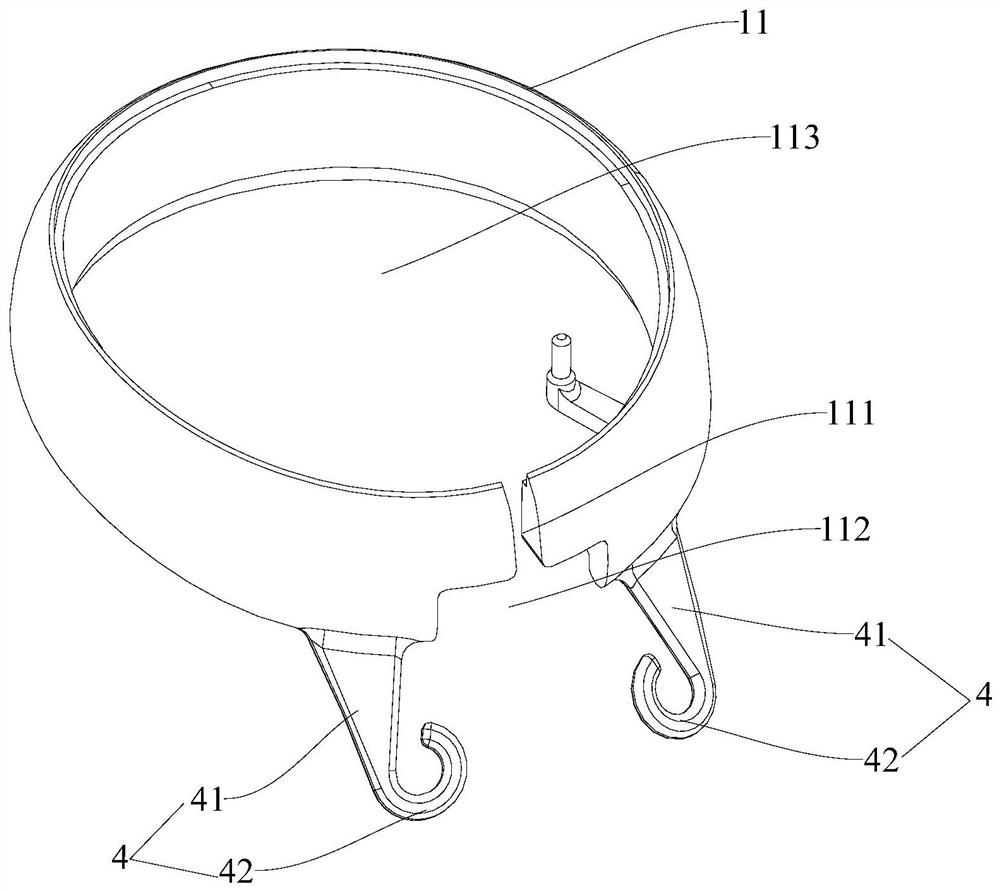
[0039] to combine figure 1 and figure 2 As shown, the annular casing 11 and the cover form the housing 1 , and the annular casing 11 defines an accommodating cavity 113 inside which electronic devices can be accommodated. The first end of the stimulation circuit assembly 2 forms an electronic device package, and the electronic device package is accommodated in the accommodating cavity 113, and the sec...


PUM


Abstract

The invention discloses an implantable retinal electric stimulator and its implant body. The implant body comprises: an annular shell, which defines an accommodating cavity; a stimulating circuit assembly, whose first end forms an electronic The device packaging body, the electronic device packaging body is accommodated in the accommodating cavity, the second end of the stimulating circuit assembly forms a stimulating end, and the stimulating end extends outward from the annular casing; the suture hook is used to attach the annular casing to the The sclera is fixed on the sclera, and the number of suture hooks is two, both of which are connected to the annular shell, and the suture hooks are non-closed loop structures, and the two suture hooks are arranged on the same side of the annular shell. The present invention only designs suture hooks on the same side of the annular shell, and the opposite side of the suture hook on the annular shell can be fixed by wrapping the conjunctiva outside the sclera, which reduces suture points while ensuring that the implant is fixed on the sclera , can reduce the difficulty of suturing during the operation, and reduce the trauma to the eyes.

Description

technical field [0001] The invention relates to the technical field of implantable medical devices, in particular to an implant body of an implantable retinal electrical stimulator and the implantable retinal electrical stimulator having the same. Background technique [0002] The implantable retinal electrical stimulator is an implanted medical device designed to help patients with retinal lesions regain light and vision. The formation of normal vision is that the photoreceptor cells (such as cone cells and rod cells) on the retina convert light stimulation into electrical signals, and after encoding by the cells of each layer of the retina (such as horizontal cells, bipolar cells, ganglion cells, etc.) , which transmit nerve impulses to the visual cortex. [0003] One design commonly used today is to implant microelectrode implants into the surface of the retina to help patients with degenerative diseases of the outer retina, such as retinitis pigmentosa and age-related m...

Claims


Application Information

Patent Timeline
Patent Type & Authority Patents(China)
IPC IPC(8): A61N1/05
CPCA61N1/0543
Inventor 戴聿昌庞长林
Owner INTELLIMICRO MEDICAL CO LTD
Why Eureka
Try Eureka