Forming device for disc-class thin-wall nut
A nut and thin-walled technology, applied in the field of disc thin-walled nut forming devices, can solve the problems of low production efficiency, large number of equipment, long process cycle, etc.
Active Publication Date: 2020-08-28
WUHAN POLYTECHNIC UNIVERSITY
11 Cites 2 Cited by
AI-Extracted Technical Summary
Problems solved by technology
Therefore, in the prior art, the forming method of disc-type thin-walled nuts requires a ...
Method used
In order to make the area to be drawn of the blank plate 1000 correspond to the drawn through hole a, referring to Fig. 4, the upper end surface of the die 212 is also provided with a positioning plate 8, and the positioning plate 8 Positioning grooves are arranged on it, and the positioning grooves are used for placing the rough plate 1000, so that the area to be drawn of the rough plate 1000 corresponds to the drawing through hole a, which facilitates the drawing of the rough plate 1000. Precise deep drawing.
Referring to Fig. 1, described lower mold base 21 comprises lower template 211 and die 212, and described lower template 211 is fixedly installed on described support 1, and the upper end surface of described lower template 211 is provided with first via hole , the die 212 is arranged on the upper end surface of the lower template 211, and the upper end face of the die 212 is provided with a second via hole corresponding to the first via hole, and the upper end face of the die 212 is used for For the blank plate 1000 to rest, and the first through hole and the second through hole jointly form t...
Abstract
The invention discloses a forming device for a disc-class thin-wall nut. The forming device for the disc-class thin-wall nut comprises a machine seat, a lower die, an upper die and a drilling and tapping assembly. The lower die comprises a lower die seat fixed to a machine seat, a blank plate is placed on the upper end surface of the lower die seat, and a drawing through hole extending up and downis formed in the upper end surface of the lower die seat. The upper die comprises an upper die plate located above the lower die seat, a drawing convex die arranged on the upper die plate and a blankholder located below the drawing convex die. The drilling and tapping assembly comprises a tapping drill bit located below the lower die seat. The upper die plate is driven to move downwards, the blank holder and the drawing convex die are moved downwards, the blank holder presses the edge of the blank plate, the drawing convex die penetrates through an inner hole of the blank holder and continues moving to press the to-be-drawn area of the blank plate into the drawing through hole to form a blank barrel, the tapping drill bit is driven to rotate and move upwards to extend into the drawing through hole, thereby drilling through the bottom wall of the blank barrel, and the inner wall of the blank barrel is tapped to form a connecting thread. Machining of the disc-class thin-wall nut is realized, the work procedure period is shortened, and production efficiency is improved.
Application Domain
Shaping toolsNuts +1
Technology Topic
Drill holeDrill bit +3
Image
Examples
- Experimental program(1)
Example Embodiment
[0049] The technical solutions in the embodiments of the present invention will be clearly and completely described below in conjunction with the accompanying drawings in the embodiments of the present invention. Obviously, the described embodiments are only a part of the embodiments of the present invention, rather than all the embodiments. Based on the embodiments of the present invention, all other embodiments obtained by those of ordinary skill in the art without creative work shall fall within the protection scope of the present invention.
[0050] It should be noted that if there is a directional indication (such as up, down, left, right, front, back...) in the embodiment of the present invention, the directional indication is only used to explain that it is in a specific posture (as shown in the drawings). If the specific posture changes, the relative positional relationship, movement, etc. of the components below will also change the directional indication accordingly.
[0051] In addition, if there are descriptions involving "first", "second", etc. in the embodiments of the present invention, the descriptions of "first", "second", etc. are only used for descriptive purposes, and cannot be understood as instructions or implications Its relative importance or implicitly indicates the number of technical features indicated. Therefore, the features defined with "first" and "second" may explicitly or implicitly include at least one of the features. In addition, the meaning of "and/or" in the full text includes three parallel schemes. Taking "A and/or B" as an example, it includes scheme A, scheme B, or schemes that meet both A and B. In addition, the technical solutions between the various embodiments can be combined with each other, but they must be based on what can be achieved by those of ordinary skill in the art. When the combination of technical solutions is contradictory or cannot be achieved, it should be considered that such a combination of technical solutions does not exist. , Is not within the protection scope of the present invention.
[0052] Disc thin-walled nuts are mainly connected parts formed by drawing, punching and threading from the blanked sheet. The disc thin-walled nuts are commonly used in automobiles, motorcycles, bicycles, etc. Increase in quantity The market demand for this nut is no less than 1 billion pieces per year. In the prior art, the disk-type thin-walled nut requires different processing molds for deep drawing, punching, and thread processing, and the processing equipment needs to be replaced during the processing. As a result, the disk-type thin-walled nut The forming process requires a large number of molds and equipment, a long process cycle, and low production efficiency.
[0053] In view of this, the present invention provides a disk thin-walled nut forming device, wherein: Figure 1 to Figure 4 It is a schematic structural diagram of an embodiment of a disk thin-walled nut forming device provided by the present invention.
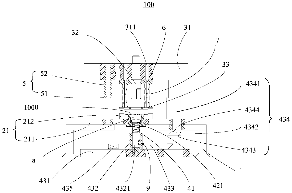
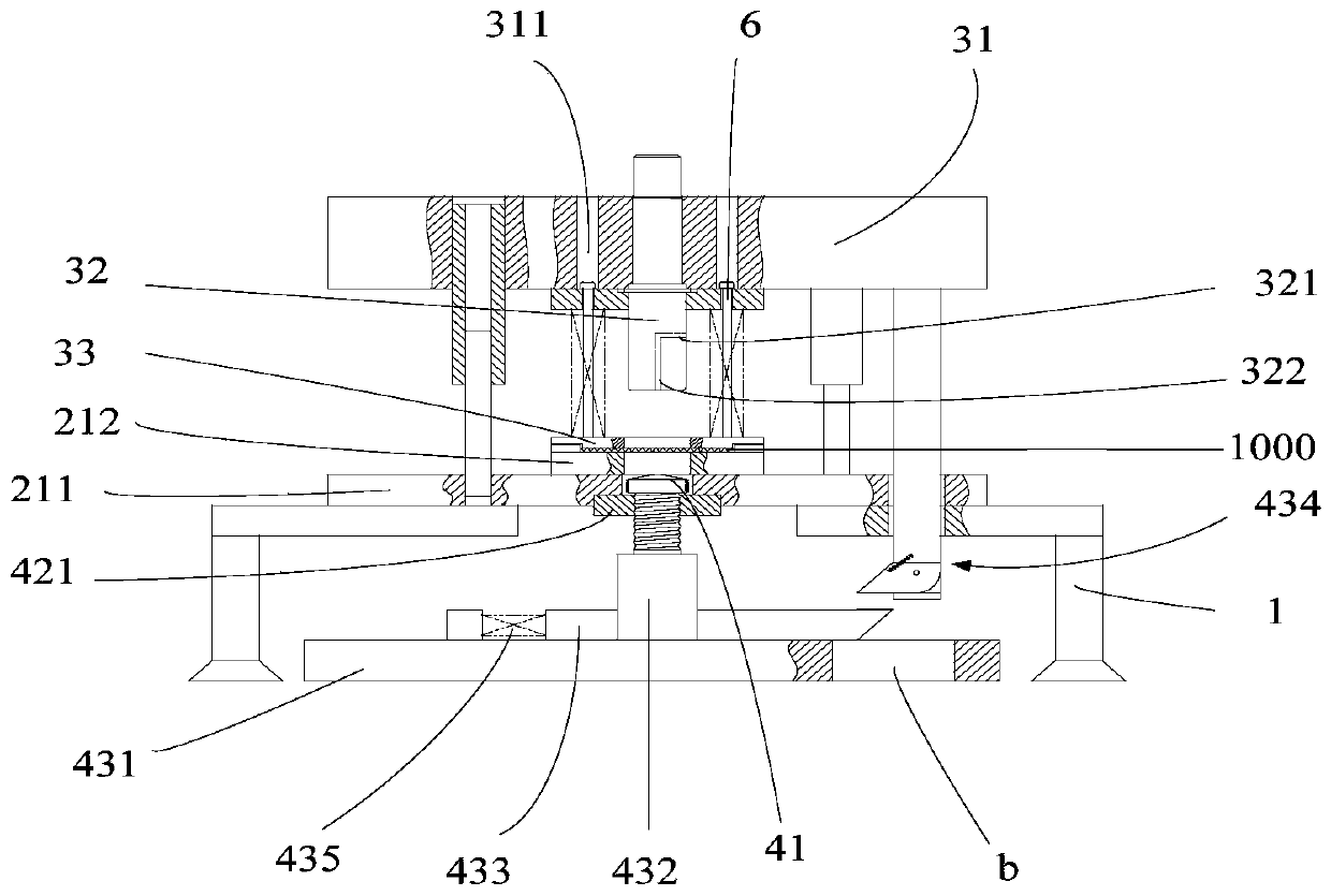
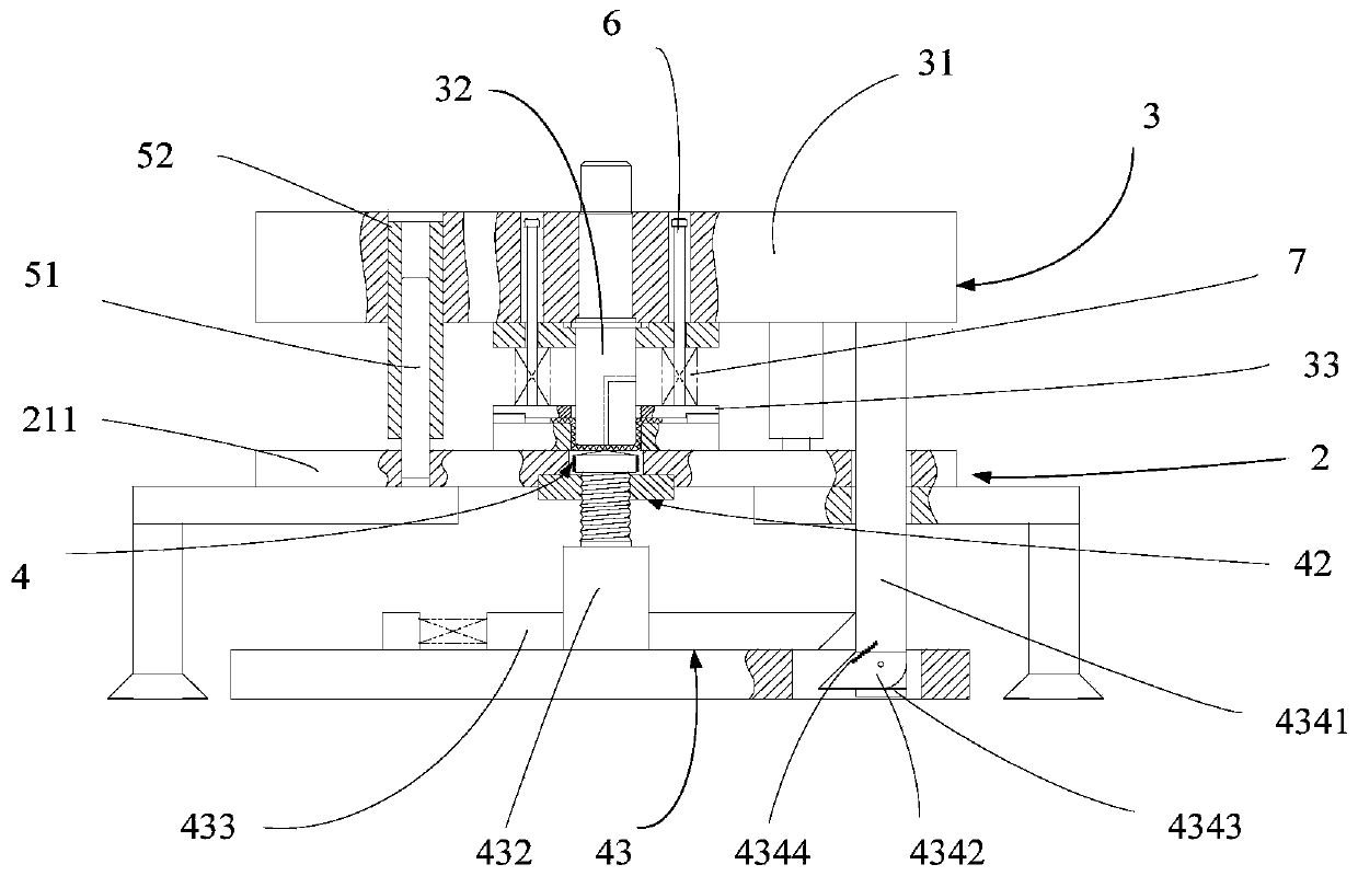
[0054] See figure 1 , The disk thin-walled nut forming device 100 includes a base 1, a lower mold 2, an upper mold 3, and a drilling and tapping assembly 4, and the lower mold 2 includes a lower mold base 21 fixedly mounted on the base 1. , The upper end surface of the lower mold base 21 is used for placing the blank plate 1000, the upper end surface of the lower mold base 21 is provided with a drawing through hole a extending vertically, and the upper mold 3 includes a vertical movable The upper mold plate 31 installed on the base 1 and located above the lower mold base 21 is provided on the upper mold plate 31 and is provided with a drawing punch 32 corresponding to the drawing through hole a. The blank holder 33 is movably mounted to the lower end surface of the upper template 31, the blank holder 33 is located below the drawing punch 32, and the drilling and tapping assembly 4 includes a vertical and vertical movably mounted The machine base 1 is a tapping drill bit 41 located below the lower die base 21. The tapping drill bit 41 is arranged corresponding to the drawing through hole a, and is rotatably mounted to the machine base 1 along an axis extending vertically. , By driving the upper template 31 to move downwards to drive the blank holder 33 and the drawing punch 32 to move downwards, the blank holder 33 presses the periphery of the blank plate 1000 (such as figure 2 (Shown), the drawing punch 32 moves downward through the inner hole of the blank holder 33, and continues to move against the area to be drawn of the blank plate 1000 into the drawing through hole a Form a blank tube (such as image 3 (Shown), the tapping bit 41 is driven to rotate and movably extends upward into the drawing through hole a, and the bottom wall of the blank barrel is drilled through the tapping bit 41, and the blank barrel Tapping in the inner wall of the machine to form a connecting thread (such as Figure 4 Shown) to get as Figure 5 The shown thin-walled nut realizes that the deep-drawing, punching and threading process of the disc-like thin-walled nut can be completed by the disc-like thin-walled nut forming device 100, which reduces the number of molds and equipment used, and shortens The process cycle improves production efficiency.
[0055] In order to enable the upper mold plate 31 to be movably installed on the base 1 in the vertical direction, specifically, in the embodiment of the present application, a guide assembly 5 is provided between the lower mold base 21 and the upper mold plate 31, The guide assembly 5 includes a guide post 51 extending in the up and down direction and a guide tube 52 adapted to the guide post 51. One of the guide post 51 and the guide tube 52 is provided in the The upper mold plate 31, the other is set on the lower mold base 21, by driving the upper mold plate 31 to make the guide column 51 move along the guide cylinder 52, so as to realize the movable installation of the upper mold plate 31 in the vertical direction 于The machine base 1.
[0056] It should be noted that there are many ways to drive the upper template 31 to move, such as air cylinders, ball screws, etc., which are not limited in this application.
[0057] Specifically, refer to figure 2 , The tapping bit 41 includes a drill bit string, the end of the drill bit string is formed with a drilling edge for drilling, and the side portion of the drill bit string is formed with a tapping blade for tapping. The tapping bit 41 can realize the drilling and tapping of the disk-type thin-walled nut, avoiding the replacement of equipment and shortening the process cycle.
[0058] In order to realize that the blank holder 33 presses the periphery of the blank plate 1000, the lower end surface of the upper template 31 is provided with a plurality of mounting holes 311 along the vertical direction, and the plurality of mounting holes 311 are arranged at intervals. On the peripheral side of the drawing punch 32, each of the multiple mounting holes 311 includes a first hole section with a larger aperture located above and a second hole section with a smaller aperture located below, so that the first hole An upward stepped surface is formed between the second hole section and the second hole section. A crimping screw 6 is inserted into the plurality of mounting holes 311, and the head of the crimping screw 6 abuts the stepped surface, The threaded end of the crimping screw 6 penetrates from the corresponding second hole section to be connected to the crimping ring 33, and between the lower end surface of the upper template 31 and the crimping ring 33 is provided A plurality of first elastic elements 7, and a plurality of the first elastic elements 7 are respectively sleeved on a corresponding plurality of the crimping screws 6, so that when the upper template 31 moves downward, it drives the The crimping ring 33 moves downwards to contact the blank plate 1000. When the upper template 31 continues to move downwards, the head of the crimping screw 6 moves along the first hole section, and the first hole section An elastic element 7 is in a compressed state, so that the blank holder 33 presses the periphery of the blank plate 1000 to prepare for the subsequent drawing process.
[0059] In order to avoid deformation of the blank cylinder formed during the drawing process, the side surface of the drawing punch 32 is provided with a first exhaust hole 321, and the lower surface of the drawing punch 32 is provided with a first exhaust hole 321. Two vent holes 322, the first vent hole 321 communicates with the second vent hole 322, and this arrangement facilitates the drawing punch 32 to move out of the drawing through hole a and avoids The blank cylinder formed by deep drawing is deformed, which affects the processing of the disc thin-walled nuts.
[0060] Reference figure 1 The lower mold base 21 includes a lower mold plate 211 and a concave mold 212, the lower mold plate 211 is fixedly installed on the machine base 1, the upper end surface of the lower mold plate 211 is provided with a first through hole, and the concave mold 212 Set on the upper end surface of the lower template 211, the upper end surface of the concave mold 212 is provided with a second via hole corresponding to the first via hole, and the upper end surface of the concave mold 212 is used for placing the blank plate 1000 , And the first via hole and the second via hole jointly form the deepened via hole a, and this arrangement facilitates the maintenance and replacement of the lower mold base 21.
[0061] In order to make the area to be drawn of the blank plate 1000 correspond to the drawn through hole a, refer to Figure 4 The upper end surface of the concave mold 212 is also provided with a positioning plate 8, and a positioning groove is provided on the positioning plate 8. The positioning groove is used for placing the blank plate 1000 so that the blank plate 1000 is The drawing area corresponds to the drawing through hole a, which facilitates the precise drawing of the blank plate 1000.
[0062] In order to realize the rotation and upward movement of the tapping bit 41, refer to image 3 The drilling and tapping assembly 4 also includes a drive assembly, the drive assembly includes a linear drive mechanism 42 and a rotation drive mechanism 43. The linear drive mechanism 42 drives the tapping bit 41 to move in the up and down direction, and passes through the The rotation driving mechanism 43 drives the tapping bit 41 to rotate along an axis extending in the up and down direction, so that the tapping bit 41 is movable in the up and down direction and rotates along the axis that extends in the up and down direction.
[0063] Reference figure 1 The lower mold base 21 includes a lower mold plate 211 fixedly mounted on the machine base 1, the rotation driving mechanism 43 includes a base 431, a gear 432, a rack 433 and a power mechanism 434, and the base 431 is located on the lower Below the template 211, the gear 432 has a rotating shaft 4321 extending in the vertical direction, the rotating shaft 4321 is rotatably mounted on the upper end surface of the base 431, and the upper end of the rotating shaft 4321 is fixed to the tapping bit 41 Connected, the rack 433 is movably mounted on the upper end surface of the base 431 in a horizontal direction, and is externally meshed with the gear 432, and the power mechanism 434 drives the rack 433 to move to drive the gear 432 Rotation, because the upper end of the rotating shaft 4321 is fixedly connected to the tapping bit 41, so as to drive the tapping bit 41 to rotate.
[0064] There are many ways to drive the rack 433 to move, for example, the rack 433 is driven to move by air cylinders, hydraulic cylinders, ball screws, etc., specifically, refer to Figure 1 to Figure 2 In the embodiment of the present application, one end of the rack 433 is a driving end, and the driving end is inclined in the vertical direction to form a first driving slope facing the base 431, and the power mechanism 434 It includes a driving rod 4341 that extends in the up and down direction. The upper end of the driving rod 4341 is fixed to the lower end surface of the upper template 31. The lower end of the driving rod 4341 is hingedly mounted with a driving block 4342. The driving block 4342 is provided with a second driving slope that is in contact with the first driving slope, the driving rod 4341 is located below the driving block 4342, and a baffle 4343 is protruding from the baffle 4343. The lower surface of the block 4342 resists, the driving rod 4341 is located above the driving block 4342 and a reset elastic member 4344 is provided between the driving block 4342, and the base 431 corresponds to the driving rod 4341 with an escape hole b. , Wherein, when the upper template 31 moves downward, the driving rod 4341 is moved downward through the avoiding hole b, the driving block 4342 rotates upward to avoid the first driving slope, and the driving rod 4341 Continue to move downward until the driving block 4342 is under the rack 433, the reset elastic member 4344 resets the driving block 4342 to rotate downward to abut the upper end surface of the baffle 4343 to complete the In the drawing of the blank plate 1000, the upper template 31 moves upward to drive the drive rod 4341 upward, and the second drive slope abuts the first drive slope to drive the rack 433 to move. The rack 433 drives the gear 432 to rotate, and the gear 432 drives the tapping bit 41 to rotate.
[0065] Reference figure 2 The rack 433 has a reset end opposite to the driving end, and a second elastic element 435 is provided on the upper end surface of the base 431, and the second elastic element 435 is provided along the extending direction of the rack 433. One end of the second elastic element 435 is fixed to the base 431, and the other end of the second elastic element 435 is fixed to the reset end of the rack 433. This arrangement is so arranged that when the drive rod 4341 continues to move upward to the When the second driving slope is separated from the first driving slope, the second reset elastic element resets the rack 433 to the initial position to prepare for the next processing of the disk-type thin-walled nut.
[0066] Reference Figure 1 to Figure 2 , The linear drive mechanism 42 includes a feed nut 421 installed on the lower end surface of the machine base 1, the threaded hole of the feed nut 421 is provided corresponding to the drawing through hole a, and the lower end of the tapping bit 41 The outer surface is provided with external threads, and the lower end of the tapping bit 41 is threadedly installed in the feeding nut 421, so that when the rack 433 drives the gear 432 to rotate, the gear 432 makes the The tapping bit 41 rotates because the lower end of the tapping bit 41 is threadedly installed in the feeding nut 421, and the feeding nut 421 is fixed to the lower end surface of the base 1, so that the tapping bit 41 has an up-and-down movement stroke. When the tapping bit 41 moves upwards, it can drill through the bottom wall of the blank barrel, and tap the inner wall of the blank barrel to form a connecting thread. After processing, the tapping drill 41 moves down to the initial position to prepare for the next working of the disc thin-walled nut.
[0067] In order to realize that the tapping bit 41 rotates with the gear 432 and can move up and down, refer to figure 1 A connecting structure 9 is provided between the inner hole wall surface of the gear 432 and the outer surface of the rotating shaft 4321, and the connecting structure 9 includes a key groove extending in the up and down direction and a key matching the key groove. One of the keyway and the key is provided on the wall surface of the inner hole of the gear 432, and the other is provided on the rotating shaft 4321. The arrangement is so arranged that the keyway is matched with the key so that the rotating shaft 4321 rotates with the gear 432 and can slide up and down. Because the tapping bit 41 is fixedly connected to the upper end of the rotating shaft 4321, the tapping bit 41 rotates with the gear 432 and moves up and down. activity.
[0068] The above descriptions are only the preferred embodiments of the present invention, and do not limit the scope of the present invention. Under the concept of the present invention, equivalent structural transformations made by using the contents of the description and drawings of the present invention, or directly/indirectly applied to Other related technical fields are included in the scope of patent protection of the present invention.
PUM


Description & Claims & Application Information
We can also present the details of the Description, Claims and Application information to help users get a comprehensive understanding of the technical details of the patent, such as background art, summary of invention, brief description of drawings, description of embodiments, and other original content. On the other hand, users can also determine the specific scope of protection of the technology through the list of claims; as well as understand the changes in the life cycle of the technology with the presentation of the patent timeline. Login to view more.