
Fault diagnosis and control method of automobile vacuum pump

A technology of fault diagnosis and control method, applied in the direction of brakes, vehicle parts, brake safety systems, etc., can solve the problem of inability to ensure the normal operation of the vacuum pump safely, efficiently and quickly, inability to provide the maintenance personnel with the cause of the failure, and the degree of fault diagnosis of the vacuum pump is simple, etc. problems, to achieve the effect of improving safety performance and braking performance, in-depth and comprehensive fault diagnosis, and safer and more stable operation.

Active Publication Date: 2020-08-28
YIBIN COWIN AUTO CO LTD
View PDF5 Cites 14 Cited by
  • Summary
  • Abstract
  • Description
  • Claims
  • Application Information

AI Technical Summary

Problems solved by technology

[0002] At present, the research on the control and fault diagnosis of automotive vacuum pumps is more inclined to the development of hardware optimization, and the research in the field of strategy is not perfect
At present, the hardware technology is relatively mature, and the cost of continuing to optimize the hardware is relatively high for automotive research, and the expected effect is not very significant; the control and diagnosis strategies of traditional vacuum pumps are in the input link, intermediate control link (such as fault handling), and output link etc. are not perfect enough to ensure the normal operation of the vacuum pump safely, efficiently and quickly; traditional vacuum pumps consider the two processes of control and diagnosis together, resulting in too cumbersome control process when the vacuum pump is running in the non-fault stage; the fault diagnosis range of traditional vacuum pumps is too large It is too small to meet the needs of fault diagnosis; the fault diagnosis of traditional vacuum pumps is too simple and cannot provide specific fault causes to maintenance personnel

Method used


Image

  • Fault diagnosis and control method of automobile vacuum pump
  • Fault diagnosis and control method of automobile vacuum pump
  • Fault diagnosis and control method of automobile vacuum pump

Examples


Embodiment Construction

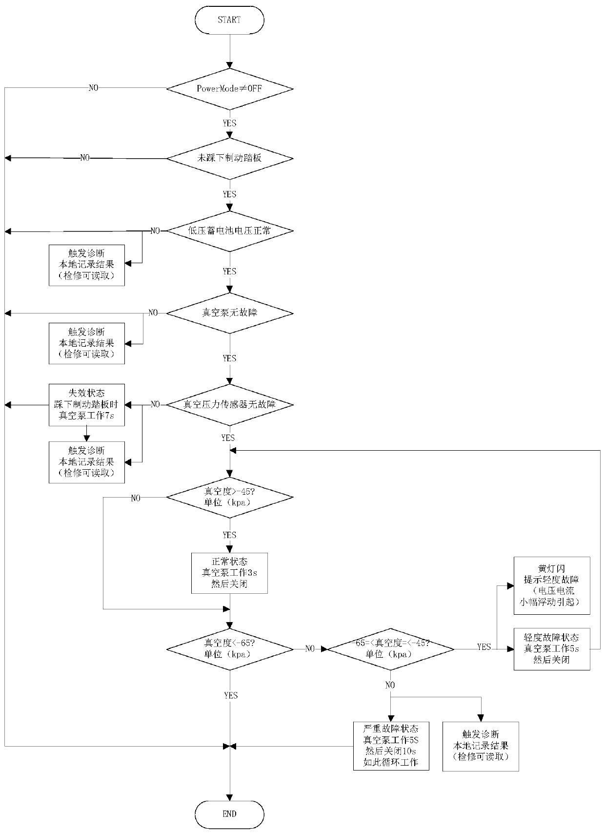
[0026] The specific implementation manner of the present invention will be described in further detail below by describing the best embodiment with reference to the accompanying drawings.

[0027] The purpose of the present invention is to formulate a more comprehensive vacuum pump control and diagnosis strategy, to efficiently and quickly control the normal operation of the vacuum pump, to better assist automobile braking and ensure safety.

[0028] Vacuum booster system, mainly including: automotive low-voltage battery, vacuum pressure sensor, vacuum pump, booster system controller, brake pedal, automotive power switch

[0029] The scheme is as follows:

[0030] The VCU controls the switch of the vacuum pump according to the collected vacuum pressure value, maintains the vacuum within a certain range, and ensures the normal operation of the brake booster system. In addition, fault diagnosis and treatment are performed on vacuum pressure sensors and vacuum pumps to reduce po...


PUM


Abstract

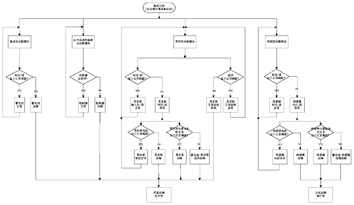
The invention discloses a fault diagnosis and control method of an automobile vacuum pump system. The method comprises the steps: after a vehicle is started and a brake pedal is not stepped on, executing the starting fault detection step of a vacuum pump system, and respectively detecting the fault states of a low-voltage storage battery, a power assisting system controller, a vacuum pump and a vacuum degree sensor in the vacuum pump system; then storing fault codes and giving out fault warning. The method has the advantages that the diagnosis accuracy is high, the control is reasonable, and the control and diagnosis of the vacuum pump system can be more comprehensively and reliably realized.

Description

technical field [0001] The invention relates to the technical field of automobile vacuum systems, in particular to a fault diagnosis and control method of an automobile vacuum pump. Background technique [0002] At present, the research on the control and fault diagnosis of automotive vacuum pumps is more inclined to the development of hardware optimization, and the research in the field of strategy is not perfect. At present, the hardware technology is relatively mature, and the cost of continuing to optimize the hardware is relatively high for automotive research, and the expected effect is not very significant; the control and diagnosis strategies of traditional vacuum pumps are in the input link, intermediate control link (such as fault handling), and output link etc. are not perfect enough to ensure the normal operation of the vacuum pump safely, efficiently and quickly; traditional vacuum pumps consider the two processes of control and diagnosis together, resulting in ...

Claims


Application Information

Patent Timeline
Patent Type & Authority Applications(China)
IPC IPC(8): B60T17/22B60T13/52
CPCB60T13/52B60T17/22
Inventor 李果郭军曾彬余苧仕何伟
Owner YIBIN COWIN AUTO CO LTD
Learn More