Dynamic headlamp lighting performance testing method based on whole vehicle
A technology for dynamic testing and headlights. It is applied to the alignment of automobile headlights, the testing of machine/structural components, and the testing of optical instruments. Problems such as deviations in lighting effects can be achieved to promote the development of automotive lighting technology, eliminate influences, and improve accuracy
- Summary
- Abstract
- Description
- Claims
- Application Information
AI Technical Summary
Problems solved by technology
Method used
Image
Examples
Embodiment 1
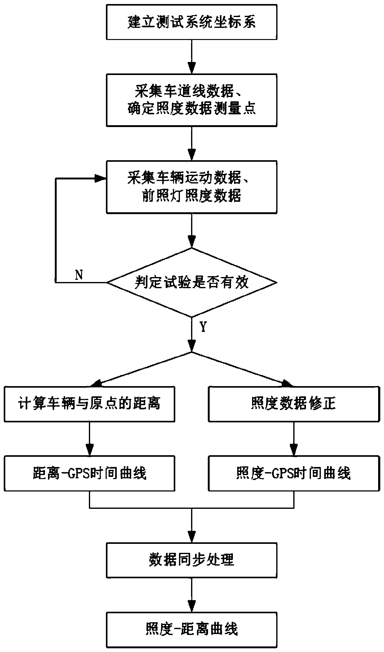
[0049] like figure 1 As shown, a kind of dynamic testing method based on vehicle headlight lighting performance of the present embodiment comprises the following steps:
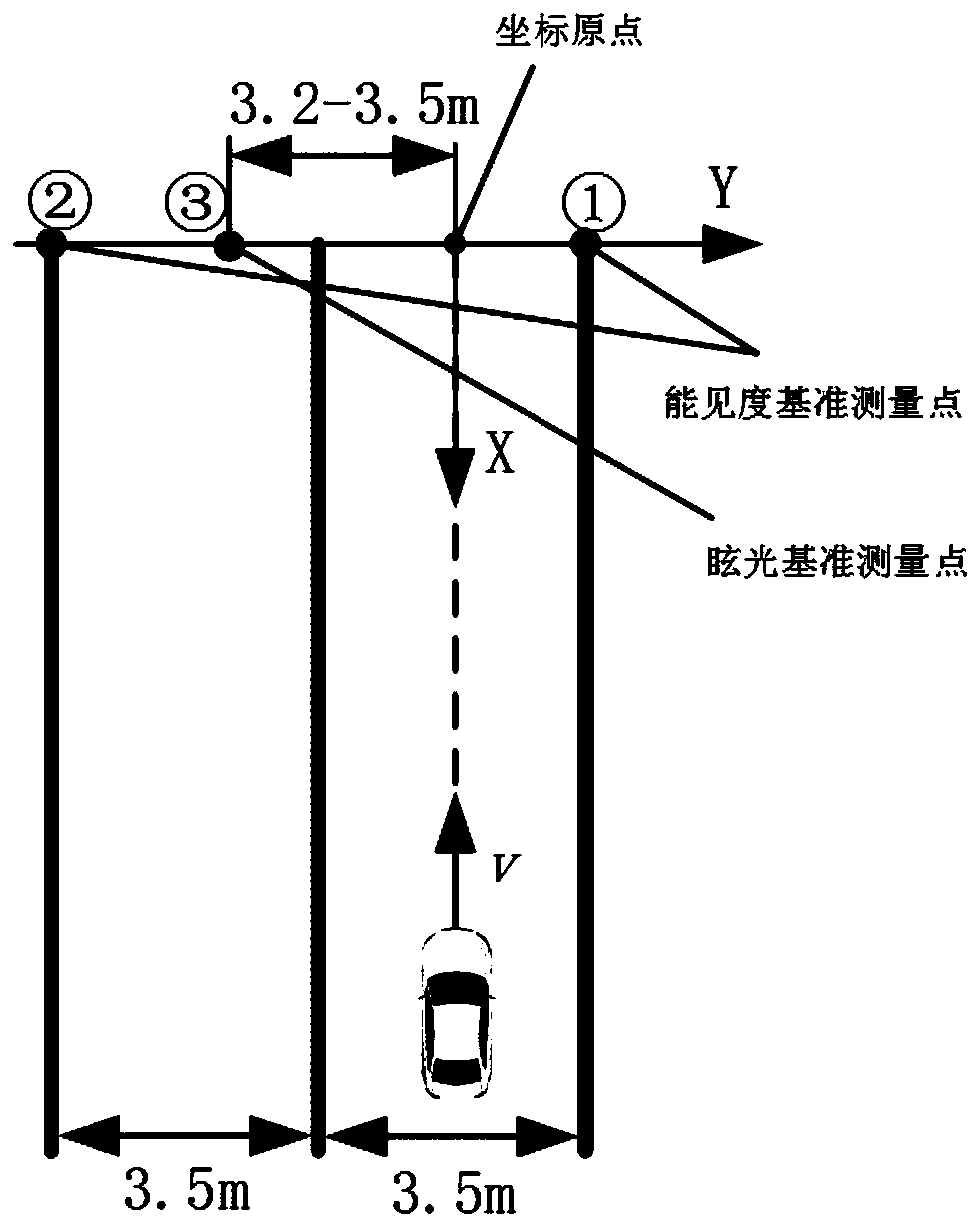
[0050] S1, such as figure 2As shown, determine the track of test, in the present embodiment with two adjacent and respectively long 200-250m, the straight road of wide 3.5-3.75m is as the track of test; The 3.5m straight road is used as the test lane; mark the lane line in the center of the lane where the vehicle is located, record the coordinates of the lane line, take the point along the lane line as the end point of the vehicle’s first preset length, and set the end point of the drive as As the coordinate origin, set up the test system coordinate system; in the present embodiment, the first preset length is 250m, in other embodiments, the first preset length is determined with the length of the lane, such as a long 200m lane, the first preset length Let the length be 200m. In this embodiment, the lane ...
Embodiment 2
[0070] The difference between this embodiment and Embodiment 1 is that in this embodiment, when a vehicle-based dynamic test method for curve lighting performance of headlights is applied to the curve test, a length of 100-150 m and a width of 3.5 m is used in step S1. -3.75m single-lane curve as the test track; in this embodiment, it is specifically 120m long and 3.5m wide;
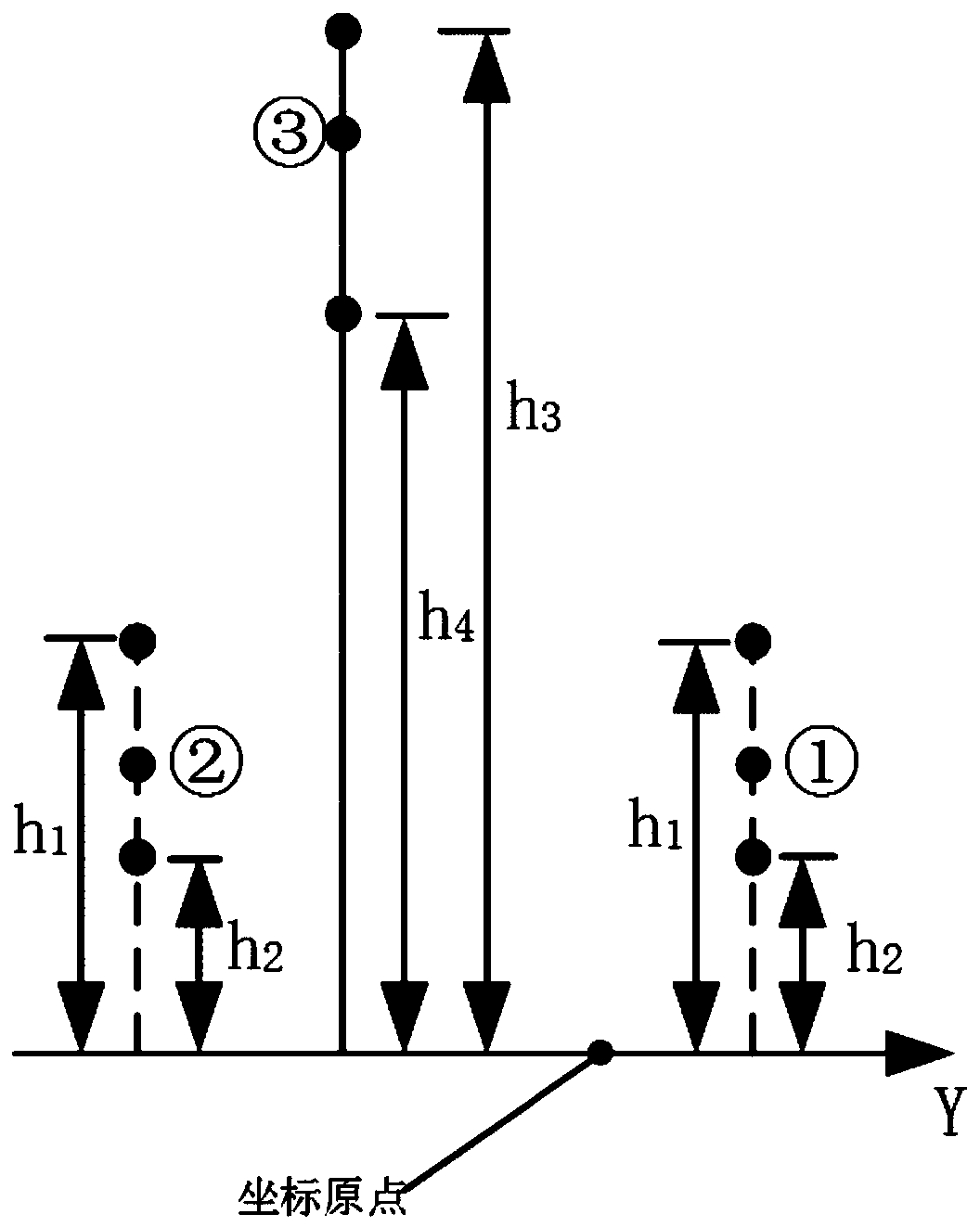
[0071] In step S3, such as Figure 4 As shown, the visibility reference measurement point is located on the boundary line of the lane, and the vertical distance from the ground is 25cm; the lateral distance between the glare reference measurement point and the lane line of the lane where the vehicle is located is 3.2-3.5cm, and 110cm from the ground; at the same time, the visibility reference measurement point , The X-axis coordinates of the glare reference measurement points projected on the ground are all 0. In this embodiment, the boundary line refers to the outermost drawn line of the single lane. ...
PUM
 Abstract
Description
Claims
Application Information
 - R&D
- Intellectual Property
- Life Sciences
- Materials
- Tech Scout
- Unparalleled Data Quality
- Higher Quality Content
- 60% Fewer Hallucinations
Browse by: Latest US Patents, China's latest patents, Technical Efficacy Thesaurus, Application Domain, Technology Topic, Popular Technical Reports.
© 2025 PatSnap. All rights reserved.Legal|Privacy policy|Modern Slavery Act Transparency Statement|Sitemap|About US| Contact US: help@patsnap.com


