Antenna radio frequency standing wave connector

A connector and radio frequency technology, used in antenna connectors, test/measurement connectors, connections, etc., can solve the problems of poor contact of test points, low production efficiency, troublesome replacement, etc. Avoid shedding effects

Pending Publication Date: 2020-08-28
深圳东创技术股份有限公司
View PDF0 Cites 0 Cited by
  • Summary
  • Abstract
  • Description
  • Claims
  • Application Information

AI Technical Summary

Problems solved by technology

[0002] When the product is tested with a conventional PCB board structure, since the product is tested at the same time with 32 ports, the height of the PIN pin of each product will be different, and the overall flatness of the product will also be different. After the product is pressed down during the test, it cannot be guaranteed that each point is in contact. The test point, because the contact between the product and the test point does not cause the antenna standing wave test to be NG; the production efficiency is low, because the ground plane of the original test method is a fixed surface, if the product has deformation problems, the test point will cause poor contact, and the test result NG needs to be re-tested ;Connection ports and contact test points are easy to be damaged after repeated disassembly / testing, because the RF line interface and test contact points are welded on the PCB board, it will be troublesome to replace if damaged

Method used


Image

  • Antenna radio frequency standing wave connector
  • Antenna radio frequency standing wave connector
  • Antenna radio frequency standing wave connector

Examples


Embodiment Construction

[0019] The following will clearly and completely describe the technical solutions in the embodiments of the present invention with reference to the accompanying drawings in the embodiments of the present invention. Obviously, the described embodiments are only some, not all, embodiments of the present invention. Based on the embodiments of the present invention, all other embodiments obtained by persons of ordinary skill in the art without making creative efforts belong to the protection scope of the present invention.

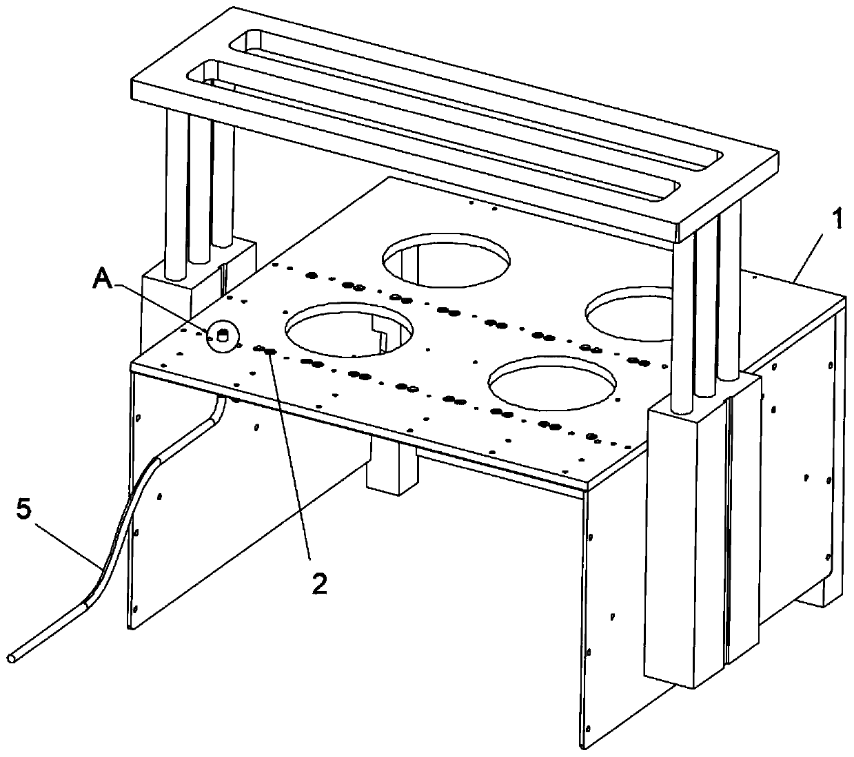
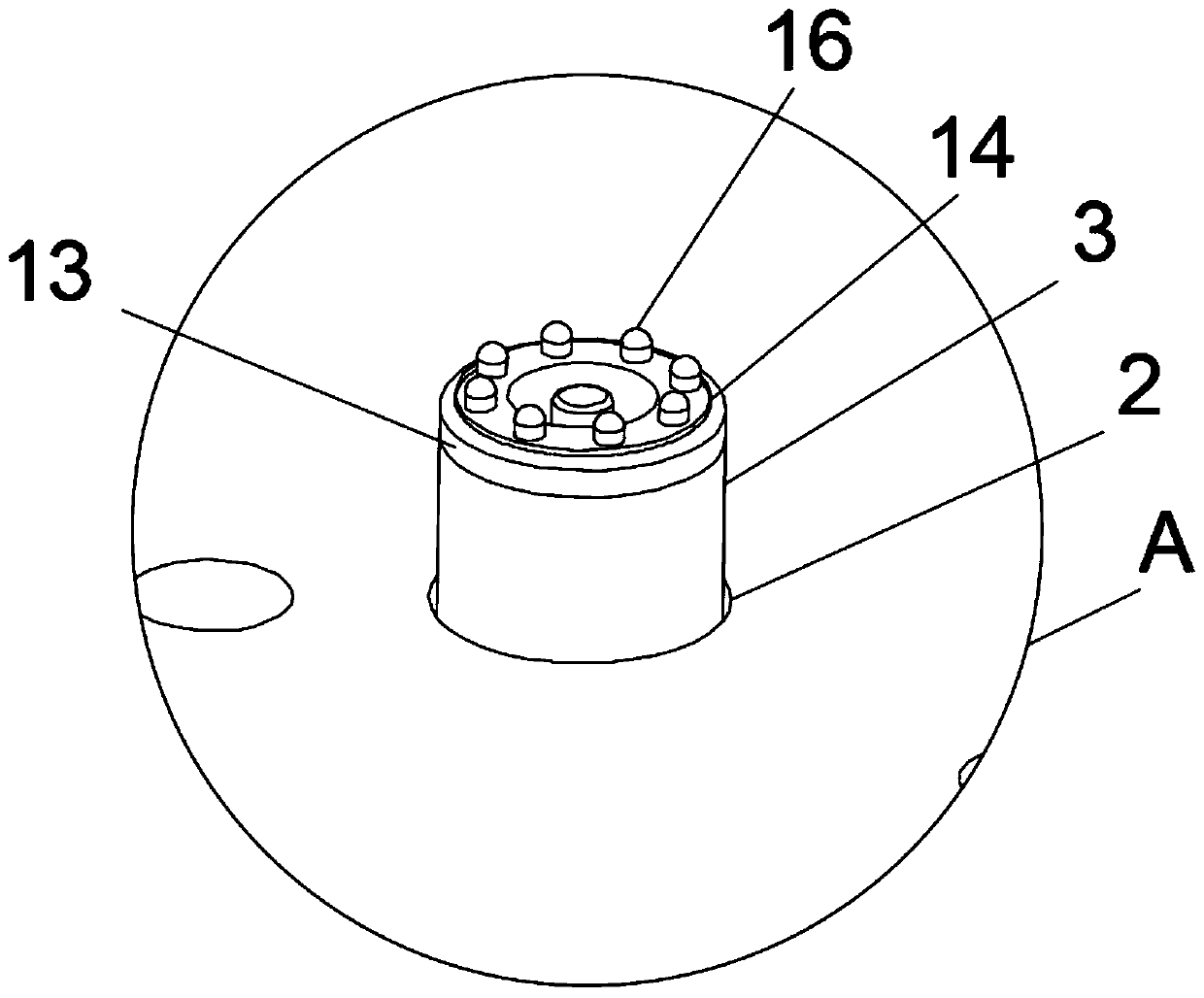
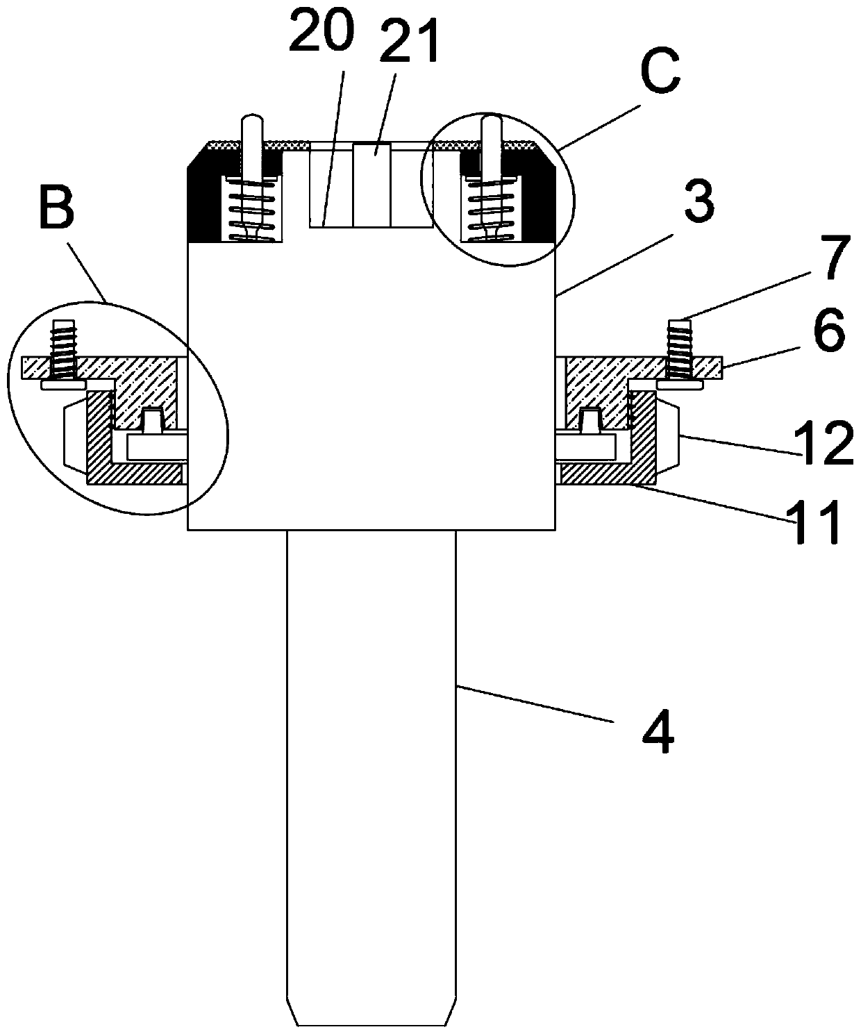
[0020] see Figure 1 to Figure 5 , the present invention provides a technical solution: an antenna radio frequency standing wave connector, including a workbench 1 and an antenna radio frequency standing wave connector body 3, the surface of the workbench 1 is provided with a mounting hole 2, and the inside of the mounting hole 2 is plugged into There is an antenna radio frequency standing wave connector body 3, and the bottom of the antenna radio frequency st...


PUM


Abstract

The invention relates to the technical field of electronic components, and particularly relates to an antenna radio frequency standing wave connector. The antenna radio frequency standing wave connector comprises a workbench and an antenna radio frequency standing wave connector body, wherein a mounting hole is formed in the surface of the workbench, the antenna radio frequency standing wave connector body is inserted into the mounting hole, a radio frequency line connecting port is formed in the bottom of the antenna radio frequency standing wave connector body, a radio frequency line is arranged at the other end of the radio frequency line connecting port, a connecting plate is arranged on the outer side of the antenna radio frequency standing wave connector body in a sleeving mode, anda fixing screw is arranged on the surface of the connecting plate. The beneficial effects are PINs are inserted into the surface of the antenna radio frequency standing wave connector, the outer sideof the PIN is sleeved with a lantern ring and then is pulled by a compression spring, and the end part of the antenna radio frequency standing wave connector body is sleeved with a protective frame, so that the PIN is telescopically inserted into the surface of the antenna radio frequency standing wave connector body, a product can also be subjected to compatibility test when the surface is deformed, and the test passing rate of the product is improved.

Description

technical field [0001] The invention relates to the technical field of electronic components, in particular to an antenna radio frequency standing wave connector. Background technique [0002] When the product is tested with a conventional PCB board structure, since the product is tested at the same time with 32 ports, the height of the PIN pin of each product will be different, and the overall flatness of the product will also be different. After the product is pressed down during the test, it cannot be guaranteed that each point is in contact. The test point, because the contact between the product and the test point does not cause the antenna standing wave test to be NG; the production efficiency is low, because the ground plane of the original test method is a fixed surface, if the product has deformation problems, the test point will cause poor contact, and the test result NG needs to be re-tested ;Connection ports and contact test points are easy to be damaged after re...

Claims


Application Information

Patent Timeline
Patent Type & Authority Applications(China)
IPC IPC(8): H01R13/24H01R13/74H01R24/00
CPCH01R13/2421H01R13/2471H01R13/74H01R13/748H01R24/00H01R2201/02H01R2201/20
Inventor 康新建何旭黄国春
Owner 深圳东创技术股份有限公司
Why Eureka
Try Eureka