Sign positioning device of automatic riveting machine

A technology of positioning device and riveting machine, which is applied in the field of riveting, can solve the problems of position deviation plate relative stress conflict, increase the production and forming time of signboards, and difficult to maintain uniform rivet positions, etc., and achieve good riveting quality, economic and social benefits. Good, highly automated results

Inactive Publication Date: 2020-09-01
广州市公路实业发展有限公司 +1
View PDF0 Cites 0 Cited by
  • Summary
  • Abstract
  • Description
  • Claims
  • Application Information

AI Technical Summary

Problems solved by technology

[0002] With the rapid development of basic equipment such as roads and bridges, other facilities such as billboards and traffic signs around the road are gradually improving. The existing billboards and traffic signs are all types of signs, usually two or more There are multiple pieces, and the plates need to be connected together through the cooperation of reinforcing ribs and aluminum profiles. The existing riveting operations are mostly riveted by manual riveting guns. The signboard is large in size, and there are many positions that need to be riveted. The riveting pressure is consistent. Manual riveting operations are required to be repeated, which increases the labor intensity of personnel and increases the production and molding time of signage. At the same time, when manual riveting operations are performed manually, the riveted workpiece is positioned by manual visual inspection or other positioning tools, and the positioning accuracy is low. As a result, it is difficult to maintain a uniform rivet position, and riveting errors are prone to occur, or relative stress conflicts between the plates caused by large position deviations, resulting in signs that are prone to separation and damage to the plates after riveting, and riveting guns are used on the market. , time-consuming and labor-intensive, and the riveting efficiency is low, and riveting failure is prone to occur

Method used


Image

  • Sign positioning device of automatic riveting machine
  • Sign positioning device of automatic riveting machine
  • Sign positioning device of automatic riveting machine

Examples


Embodiment Construction

[0044] The present invention will be described in detail below in conjunction with the accompanying drawings and specific embodiments, and the present invention will be described in detail below in conjunction with the accompanying drawings and specific embodiments. To explain the present invention, but not as a limitation of the present invention.

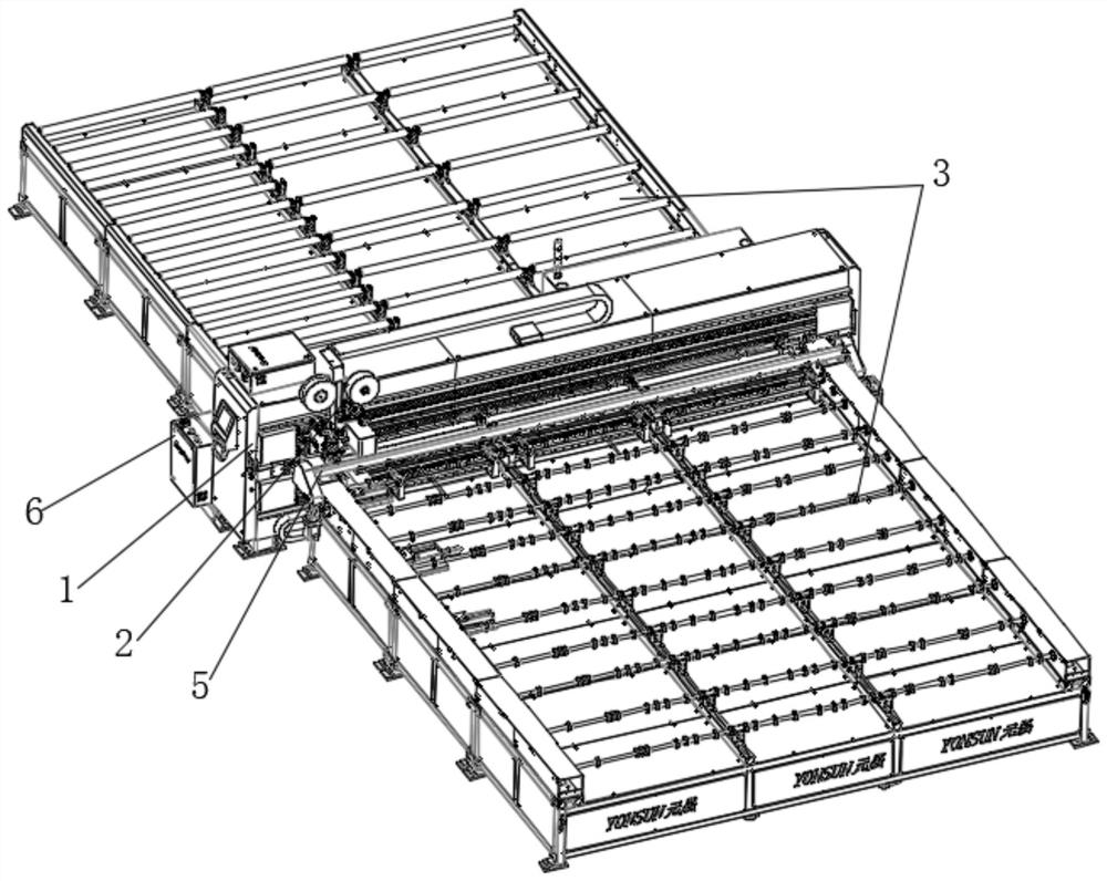
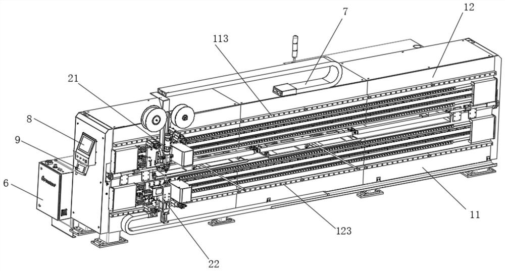
[0045] like Figure 1 to Figure 21 As shown, a signboard positioning device for an automatic riveting machine, including:

[0046] A gantry support 1, the gantry support 1 comprising a first gantry 11 and a second gantry 12; the second gantry 12 is fixedly mounted on the top surface of the first gantry 11;

[0047] A riveting mechanism 2, the riveting mechanism 2 includes a self-propelled upper riveting module 21 and a self-propelled lower riveting module 22; the self-propelled upper riveting module 21 is movably mounted on the second gantry 12; The self-propelled lower riveting module 22 is movably installed on the first gantry...


PUM


Abstract

The invention discloses a sign positioning device of an automatic riveting machine. The sign positioning device comprises a gantry support and a positioning mechanism; the gantry support comprises a first gantry frame and a second gantry frame; the second gantry frame is fixedly erected on the top surface of the first gantry frame; the positioning mechanism comprises a workpiece front-end positioning assembly and a workpiece side-edge positioning assembly; the workpiece front-end positioning assembly is used for positioning the front-end length of a workpiece; and the workpiece side-edge positioning assembly is used for positioning the side-edge length of the workpiece. According to the sign positioning device, signs in multiple sizes can be positioned, the device is wide in application range, high in positioning accuracy and high in riveting quality, the labor cost is greatly reduced, the working efficiency is improved, and the device is easy to popularize and apply and has the brighteconomic benefit and social benefit prospects.

Description

technical field [0001] The invention relates to the technical field of riveting, in particular to a signboard positioning device for an automatic riveting machine. Background technique [0002] With the rapid development of basic equipment such as roads and bridges, other facilities such as billboards and traffic signs around the road are gradually improving. The existing billboards and traffic signs are all types of signs, usually two or more There are multiple pieces, and the plates need to be connected together through the cooperation of reinforcing ribs and aluminum profiles. The existing riveting operations are mostly riveted by manual riveting guns. The signboard is large in size, and there are many positions that need to be riveted. The riveting pressure is consistent. Manual riveting operations are required to be repeated, which increases the labor intensity of personnel and increases the production and molding time of signage. At the same time, when manual riveting ...

Claims


Application Information

Patent Timeline
Patent Type & Authority Applications(China)
IPC IPC(8): B21J15/42B21J15/32B21J15/14B21J15/38B21J15/44
CPCB21J15/14B21J15/32B21J15/38B21J15/42B21J15/44
Inventor 肖华彪杨婕刘培俭金渊周群辉曾加亮
Owner 广州市公路实业发展有限公司
Why Eureka
Try Eureka