
Equipment for cutting two sides of ring-pull can

The technology of a pop-top can and equipment is applied in the field of equipment for cutting both sides of pop-top cans, which can solve the problems of low work efficiency and high danger in the cutting process, and achieve the effects of improving efficiency and saving manpower.

Pending Publication Date: 2020-09-01
彭杨杨
View PDF0 Cites 2 Cited by
  • Summary
  • Abstract
  • Description
  • Claims
  • Application Information

AI Technical Summary

Problems solved by technology

[0004] In order to overcome the disadvantages of manual batch cutting of discarded pop cans, the cutting process is highly dangerous and the work efficiency is low, the technical problem is to provide a method that can not only automatically cut pop cans safely and reliably, but also improve work efficiency. cutting equipment

Method used


Image

  • Equipment for cutting two sides of ring-pull can
  • Equipment for cutting two sides of ring-pull can
  • Equipment for cutting two sides of ring-pull can

Examples


Embodiment 1

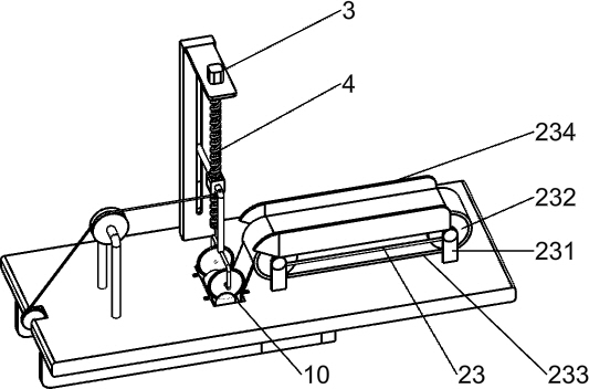
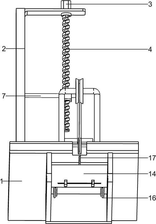
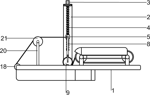
[0021] A device for cutting the sides of cans, such as Figure 1-4 As shown, it includes a base 1, a bracket 2, a motor 3, a lead screw 4, a nut 5, a slide bar 7, a connecting rod 8, an electric saw wheel 9 and a moving mechanism. A motor 3 is installed, and the front side of the top of the bracket 2 is rotatably connected to a screw 4, the output shaft of the motor 3 is connected to the top of the screw 4, the screw 4 is connected with a nut 5, and the front side of the bracket 2 has a first chute 6. A sliding rod 7 is slidingly connected to the first chute 6. The bracket 2 supports the screw 4 and the sliding rod 7. The front end of the sliding rod 7 is connected with the nut 5. A connecting rod 8 is provided on the front side of the nut 5. The lower end of connecting rod 8 is provided with electric saw wheel 9, and base 1 top right side has groove 10, and groove 10 is positioned at the just below electric saw wheel 9, and people can put pop can into groove 10, and pop can i...


PUM


Abstract

The invention relates to cutting equipment and particularly relates to equipment for cutting the two sides of a ring-pull can. The equipment for cutting the two sides of the ring-pull can aims at achieving the technical purposes that the ring-pull can can be automatically cut safely and reliably, and the working efficiency can also be improved. According to the technical scheme, the equipment forcutting the two sides of the ring-pull can comprises a base, a support, a motor and the like; and the support is installed on one side of the top of the base, the motor is connected to the top of thesupport, a lead screw is connected to one side of the top of the support in a rotating mode, the end of the lead screw is connected with an output shaft of the motor, and a nut is connected to one side of the lead screw. According to the equipment, an electric saw wheel and a conveying mechanism can be made to run by starting the motor, ring-pull cans obtained after cutting is completed can go outthrough the conveying mechanism, labor is saved, and the efficiency is improved; and the safety of a user is also guaranteed, and the ring-pull can can be clamped through a sliding plate and the electric saw wheel together so as to carry out work.

Description

technical field [0001] The invention relates to a cutting device, in particular to a device for cutting both sides of pop cans. Background technique [0002] At present, cans are common waste in our daily life. Some waste pickers often pick up cans for recycling and processing. These cans need to be cut on both sides, leaving the useful part in the middle, but the discarded cans will be manually batched Carry out cutting, its cutting process risk is high, and work efficiency is low, therefore, need to develop a kind of equipment that cuts both sides of pop can. [0003] To sum up, for the problems existing in cutting waste cans, people have developed a device that can automatically cut both sides of cans, which is not only safe and reliable, but also improves work efficiency. Contents of the invention [0004] In order to overcome the disadvantages of manual batch cutting of discarded pop cans, the cutting process is highly dangerous and the work efficiency is low, the te...

Claims


Application Information

Patent Timeline
Patent Type & Authority Applications(China)
IPC IPC(8): B23D45/00B23D47/04B23D59/00B23Q5/28
CPCB23D45/00B23D47/04B23D59/00B23Q5/28
Inventor 彭杨杨
Owner 彭杨杨
Learn More