
Transmission shaft structure and robot with same

A transmission shaft and robot technology, applied in the field of robots, can solve the problems of difficulty in the manufacture of transmission shafts, and achieve the effects of reducing the length, reducing the manufacturing cost, and reducing the processing difficulty.

Pending Publication Date: 2020-09-01
ZHUHAI GREE INTELLIGENT EQUIP CO LTD +1
View PDF6 Cites 0 Cited by
  • Summary
  • Abstract
  • Description
  • Claims
  • Application Information

AI Technical Summary

Problems solved by technology

[0005] The main purpose of the present invention is to provide a transmission shaft structure and a robot with it, so as to solve the problem that the production of the transmission shaft of the robot in the prior art is relatively difficult

Method used


Image

  • Transmission shaft structure and robot with same

Examples


Embodiment Construction

[0021] It should be noted that, in the case of no conflict, the embodiments in the present application and the features in the embodiments can be combined with each other. The present invention will be described in detail below with reference to the accompanying drawings and examples.

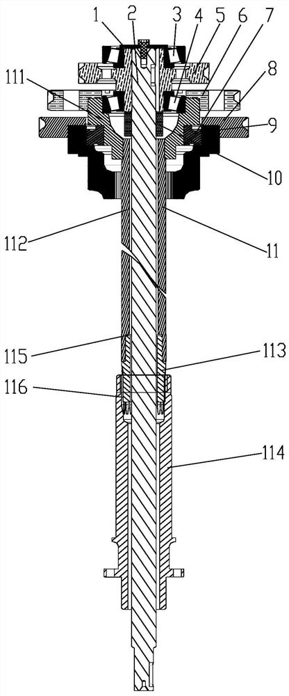
[0022] In order to solve the problem that the manufacture of the transmission shaft of the robot in the prior art is relatively difficult, the present invention provides a transmission shaft structure and a robot with it, such as figure 1 As shown, wherein, the transmission shaft structure includes: a plurality of transmission shafts, and the plurality of transmission shafts are sequentially nested along the radial direction of each transmission shaft; wherein, at least part of the transmission shafts in the plurality of transmission shafts include multi-segment drive shaft segments.

[0023] Since the transmission shaft structure includes a plurality of transmission shafts, the plurality of t...


PUM


Abstract

The invention provides a transmission shaft structure and a robot with same. The transmission shaft structure is characterized in comprising a plurality of transmission shafts which are arranged by nesting in sequence along the radial direction of each transmission shaft, wherein at least part of the plurality of transmission shafts comprise a plurality of transmission shaft sections distributed along the radial direction thereof. The invention solves the problem that the transmission shafts in a robot in the prior art are difficult in manufacturing.

Description

technical field [0001] The invention relates to the field of robots, in particular to a transmission shaft structure and a robot with the same. Background technique [0002] At present, the connection methods of industrial robots include motors directly connected to reducers, motors connected to reducers through belt transmission, motors connected to reducers through gear transmission, and the comprehensive application of gears and drive shafts. [0003] Among them, the use of the transmission shaft can well place the motor behind the robot joint, improve the load carrying capacity of the robot, and improve the rigidity of the robot body structure. [0004] However, the transmission shafts used in industrial robots are generally long shafts, which require high precision. For manufacturing, it is difficult to directly process a qualified transmission shaft with one part. Contents of the invention [0005] The main purpose of the present invention is to provide a transmissi...

Claims


Application Information

Patent Timeline
IPC IPC(8): B25J9/10F16H57/00
CPCB25J9/102F16H57/0025
Inventor 赖建林李久林钟文涛张秀峰张天翼
Owner ZHUHAI GREE INTELLIGENT EQUIP CO LTD
Features
  • Generate Ideas
  • Intellectual Property
  • Life Sciences
  • Materials
  • Tech Scout
  • Unparalleled Data Quality
  • Higher Quality Content
  • 60% Fewer Hallucinations
Learn More