A kind of polyethylene material processing equipment

A technology of material processing and polyethylene, which is applied in the field of polyethylene material processing equipment, can solve problems such as rebound jumping and collision, and achieve the effect of avoiding rebound

Active Publication Date: 2021-09-17
江苏立汉科技有限公司
View PDF6 Cites 0 Cited by
  • Summary
  • Abstract
  • Description
  • Claims
  • Application Information

AI Technical Summary

Problems solved by technology

[0003] Based on the discovery of the above-mentioned inventors, the existing polyethylene material processing equipment mainly has the following shortcomings, such as: the cutter rotates to cut the strip-shaped polyethylene material, and the granular polyethylene material after cutting will be affected. The downward force of the cutter makes the granular polyethylene material collide with the upper end surface of the cutting groove, thereby rebounding and jumping upwards, causing the granular polyethylene material to deviate outwards and fall to the outer end of the packaging bag

Method used


Image

  • A kind of polyethylene material processing equipment
  • A kind of polyethylene material processing equipment
  • A kind of polyethylene material processing equipment

Examples


Embodiment 1

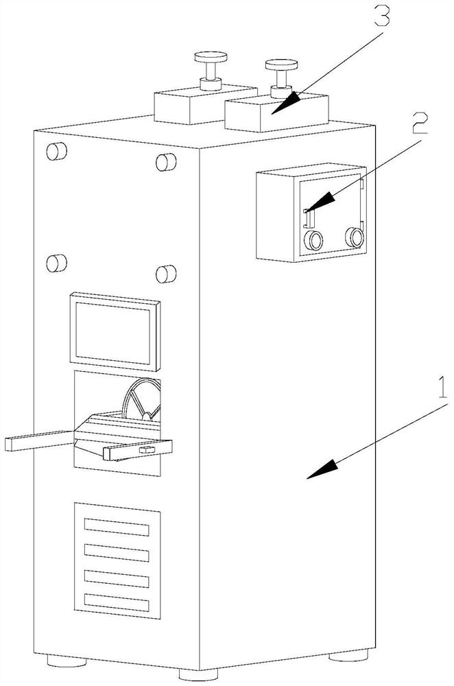
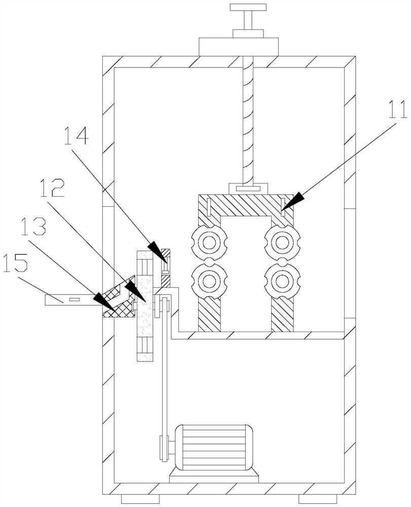
[0026] Example 1: Please refer to Figure 1-Figure 5 The specific embodiment of the present invention is as follows: its structure includes a main body 1, a control box 2, and an adjustment block 3. The side end of the main body 1 is embedded with the control box 2, and the adjustment block 3 is embedded on the top of the main body 1. The main body 1 includes a guide roller 11, a cutting block 12, a guide block 13, a pressing block 14, and a hook 15. The guide roller 11 is arranged in the middle of the main body 1, the cutting block 12 is located at the front end of the main body 1, and the guide The block 13 is embedded in the front end of the cutting block 12 , the pressing block 14 is located in the rear end of the cutting block 12 , and the hook 15 is embedded in the front end of the guide block 13 .

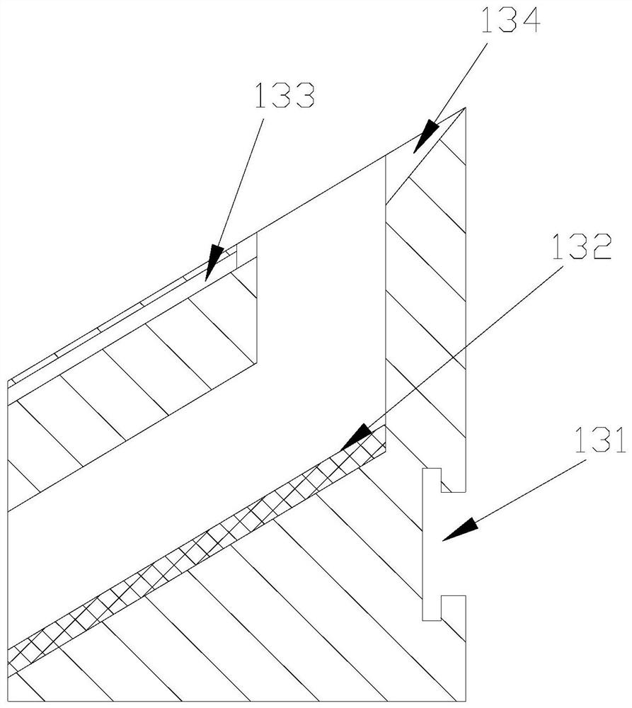
[0027] The guide block 13 includes an engaging groove 131, a feeding groove 132, a material guiding groove 133, and a dropping groove 134. The engaging groove 131 is arrange...

Embodiment 2

[0031] Example 2: Please refer to Figure 6-Figure 8 The specific embodiment of the present invention is as follows: the pressing block 14 includes a pressing groove 141, a telescopic rod 142, and a pressing body 143. At the top, the angle between the bottom of the pressing groove 141 and the horizontal plane is 30 degrees, which is beneficial for the pressing body 143 to press the strip-shaped polyethylene material, so that the strip-shaped polyethylene material bends downward, allowing the cutting block 12 to cut into Polyethylene pellets can fall straight down.

[0032] The pressing body 143 includes a support block b1, a slot b2, and a roller b3. The bottom of the support block b1 is provided with four slots b2, the slot b2 is circular, and the roller b3 is provided with four, And engaged in the slot b2, the bottom of the support block b1 is arc-shaped, which is beneficial for the roller b3 to press down the strip-shaped polyethylene material, so that the strip-shaped pol...


PUM


Abstract

The invention discloses a polyethylene material processing equipment, which includes a main body, a control box, and an adjustment block. The main body includes a guide roller, a cutting block, a guide block, a pressing block, and a hook. The front end of the main body, the guide block is embedded in the front end of the cutting block, the pressing block is located in the rear end of the cutting block, and the hook is embedded in the front end of the guide block. , the drop chute includes a support body, a bottom trough, and a baffle plate. In the present invention, the bottom of the chute is set in a V-shape, so that the fallen polyethylene particles are concentrated in the middle of the chute, and they pass through in a circular shape. The partitions arranged around the discharge port guide the polyethylene particles scattered in the bottom trough to the discharge port, so that the polyethylene particles can fall accurately into the packaging bag from the middle of the bottom trough and the discharge chute.

Description

technical field [0001] The invention relates to the field of polyethylene material equipment, in particular to polyethylene material processing equipment. Background technique [0002] In the production process of polyethylene, it is necessary to use oxygen or peroxide as an initiator to polymerize ethylene into low-density polyethylene; ethylene enters the reactor after two stages of compression. Polyethylene is polymerized under the action of initiator and initiator, and the reactants are separated under reduced pressure to recycle the unreacted ethylene. The melted polyethylene is extruded after adding plastic additives to form strips and directly enters the water tank for further processing. After cooling and solidification, it is guided by guide rollers into the cutting groove for cutting to form particles. [0003] Based on the inventors' findings above, the existing polyethylene material processing equipment mainly has the following disadvantages, such as: the cutter...

Claims


Application Information

Patent Timeline
Patent Type & Authority Patents(China)
IPC IPC(8): B29B9/06B65B1/06B65B39/00
CPCB29B9/06B65B1/06B65B39/00
Inventor 黄种胜
Owner 江苏立汉科技有限公司
Why Eureka
Try Eureka