Badminton head hole-pressing device used for badminton making

A badminton and ball-using technology, applied in climate change adaptation, metal processing, etc., can solve the problems of low work efficiency, hand soreness affecting follow-up work, laborious and other problems, and achieve the effect of high work efficiency

Active Publication Date: 2021-02-02
邹志鹏
View PDF5 Cites 0 Cited by
  • Summary
  • Abstract
  • Description
  • Claims
  • Application Information

AI Technical Summary

Problems solved by technology

[0005] In order to overcome the need to move the tool repeatedly, the hand is easy to be sore and affects the follow-up work. After a long time, it is more laborious, and people can only press out one hole at a time, resulting in low work efficiency. The technical problem of the present invention is to provide a It can replace manual pressing holes on one side of the ball head, which saves labor, and can press holes on one side of the ball head at one time, and is a ball head pressing device for badminton production with high working efficiency.

Method used


Image

  • Badminton head hole-pressing device used for badminton making
  • Badminton head hole-pressing device used for badminton making
  • Badminton head hole-pressing device used for badminton making

Examples


Embodiment 1

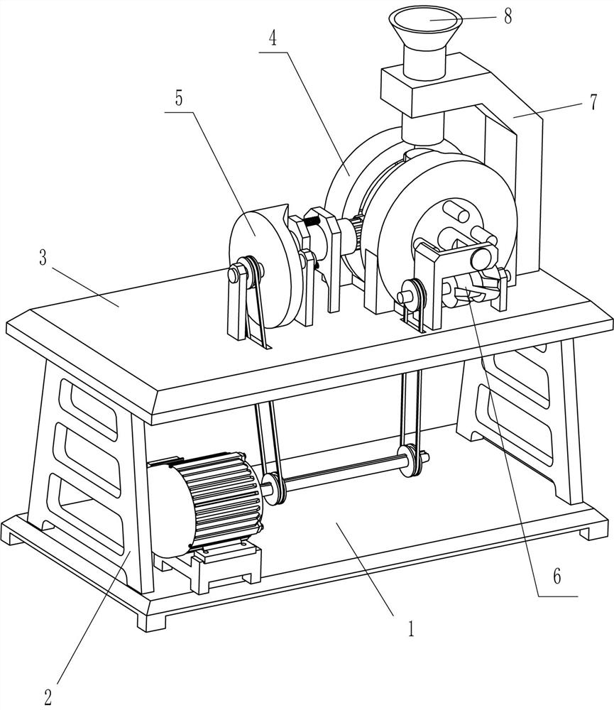
[0024] A ball head pressing hole device for making badminton, such as Figure 1-Figure 4 As shown, it includes a base 1, a stand 2, a horizontal plate 3, a feeding device 4 and a pressing device 5, the left and right sides of the top of the base 1 are fixedly connected with the stand 2, and the top of the stand 2 on the left and right sides is fixed. A horizontal plate 3 is connected, an opening is opened in the middle of the right part of the horizontal plate 3, a feeding device 4 is provided on the right side of the top of the horizontal plate 3, a pressing device 5 is arranged between the left part of the horizontal plate 3 and the left side of the top of the base 1, and The feeding device 5 cooperates with the feeding device 4.

[0025] The conveying device 4 includes a special-shaped frame 41, a first vertical plate 42, a first rotating shaft 43, a rotating cylinder 44, a limit ring 45, a second rotating shaft 46, a clamp block 47, a swash plate 48, a first spring 49 and ...

Embodiment 2

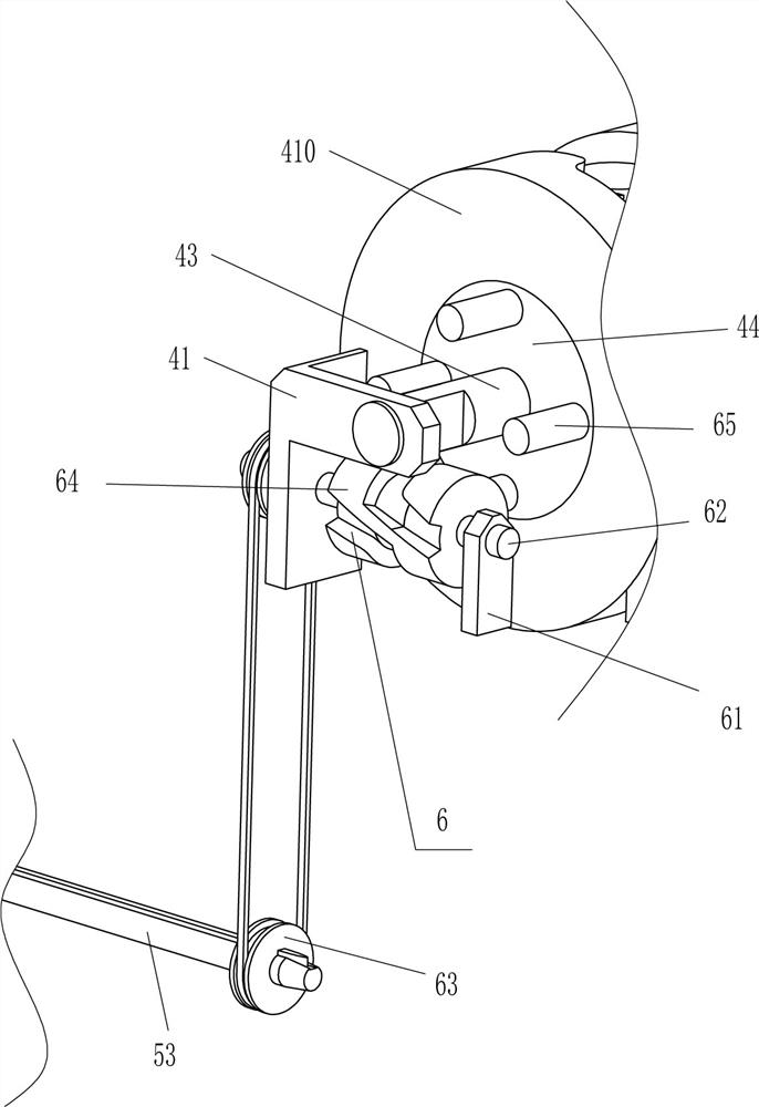
[0031] On the basis of Example 1, such as figure 1 , figure 2 and Figure 5 As shown, a driving device 6 is also included, and the driving device 6 includes a third vertical plate 61, a fifth rotating shaft 62, a second transmission assembly 63, a groove drum 64 and a contact rod 65, and the front part of the top right side of the horizontal plate 3 is fixed There is a third vertical plate 61, and a fifth rotating shaft 62 is rotatably connected between the upper part of the third vertical plate 61 and the lower part of the special-shaped frame 41. The right part of the fifth rotating shaft 62 is circumferentially fixed with a groove tube 64. The fifth rotating shaft 62 A second transmission assembly 63 is connected between the left circumference and the right circumference of the third rotating shaft 53, the second transmission assembly 63 runs through the horizontal plate 3, and four contact rods 65 are fixedly fixed on the front side of the rotating cylinder 44 at even in...

Embodiment 3

[0034] On the basis of embodiment 1 and embodiment 2, such as figure 1 As shown, it also includes an L-shaped frame 7 and a blanking tube 8, the middle of the right side of the top of the horizontal plate 3 is fixedly connected with an L-shaped frame 7, and the middle of the left part of the L-shaped frame 7 is fixedly connected with a blanking tube 8. 8 is located directly above the limit ring 45.

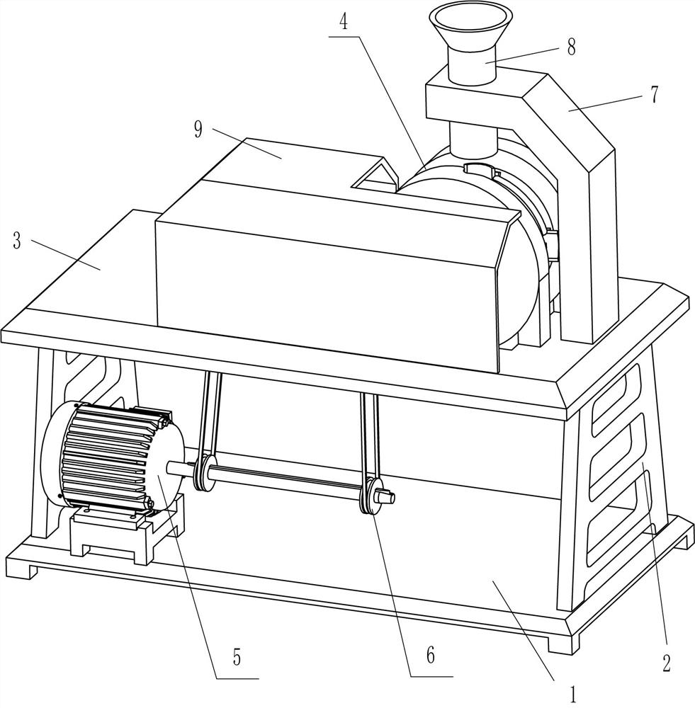
[0035] It also includes a protective case 9, the top front side of the horizontal plate 3 is fixedly connected with the protective case 9, the swash plate 57 and the puncher 59 are located in the protective case 9, and the groove tube 64 is also located in the protective case 9.

[0036] Firstly, the operator drops a ball head into the feeding pipe 8, and the ball head in the feeding pipe 8 falls between the two clamping blocks 47 above. In this way, the ball head can be accurately dropped between the two clamping blocks 47 above.

[0037] When the device is in operation, the pr...


PUM


Abstract

The invention relates to a hole-pressing device, in particular to a badminton head hole-pressing device for badminton making. The technical problem is how to design the badminton head hole-pressing device for badminton making that manual labor can be replaced to perform hole pressing on one side of a badminton head in the circumferential direction, labor is saved, holes in one side of the badminton head can be pressed in the circumferential direction at a time, and the working efficiency is high. The badminton head hole-pressing device for badminton making comprises a base and a transverse plate, wherein one side of the base is fixedly connected with vertical frames symmetrically; and the transverse plate is fixedly connected between the ends, away from the base, of the two vertical frames, and an opening is formed in the middle part of one side of the transverse plate. According to the badminton head hole-pressing device, the badminton head is placed between two clamping blocks on theupper portion; a limiting ring is pulled to rotate reversely by 90 degrees to make the badminton head rotate reversely by 90 degrees to correspond to a hole-pressing device; the clamping blocks clampthe badminton head; a reduction motor is started to rotate, and then the hole-pressing device moves rightwards to perform hole pressing on one side of the badminton head in the circumferential direction, and thus, hole pressing does not need to be manually performed on one side of the badminton head in the circumferential direction, so that the labor is saved, and the working efficiency is high.

Description

technical field [0001] The invention relates to a hole pressing device, in particular to a ball head pressing hole device for making badminton. Background technique [0002] Badminton is a sport that can be played both indoors and outdoors. According to the number of participants, it can be divided into singles and doubles, and the emerging 3-on-3. The badminton racket is composed of a racket face, a racket shaft, a handle and a joint between a racket frame and the racket shaft. The length of a racket does not exceed 680 mm, of which the length of the racket handle and racket shaft does not exceed 41 cm, the length of the racket frame is 28 cm, and the width is 23 cm. The frame is harder and the racket shaft is more elastic. During the production process of badminton, it is necessary to press holes on one side of the ball head in the circumferential direction, so that the feathers can be inserted into the holes for subsequent processing. [0003] At present, most of the h...

Claims


Application Information

Patent Timeline
IPC IPC(8): B26F1/16B26D7/02B26D7/06
CPCB26F1/16B26D7/02B26D7/0641Y02A40/90
Inventor 邹志鹏
Owner 邹志鹏
Why Eureka
Try Eureka