
A river hydroelectric power generation device with garbage collection and compression function

A hydroelectric power generation device and garbage collection technology, applied in the field of hydroelectric power generation equipment, can solve the problems of unfavorable transportation treatment, low garbage density, low efficiency, etc., and achieve the effect of facilitating subsequent transportation and utilization

Inactive Publication Date: 2021-06-11
南京溧水高新产业股权投资有限公司
View PDF0 Cites 0 Cited by
  • Summary
  • Abstract
  • Description
  • Claims
  • Application Information

AI Technical Summary

Problems solved by technology

[0002] The current hydropower generation is usually based on rivers and lakes. Since small rivers usually have a small water flow, it is difficult to generate electricity. Therefore, the utilization of water resources in small flowing rivers has yet to be developed. On the other hand, most of these small rivers There are all kinds of garbage floating, and there is a possibility that the garbage will be stirred into the fan blades and damage the generator during the power generation process. At the same time, most of the garbage in the river is salvaged manually, which is inefficient, and the garbage floating on the water surface is relatively small in density and large in size. After collection and salvage, the volume is large, which is not conducive to subsequent transportation and processing

Method used


Image

  • A river hydroelectric power generation device with garbage collection and compression function
  • A river hydroelectric power generation device with garbage collection and compression function
  • A river hydroelectric power generation device with garbage collection and compression function

Examples


Embodiment Construction

[0021] All features disclosed in this specification, or steps in all methods or processes disclosed, can be combined in any way, except for mutually exclusive features and or steps.

[0022] Combine below Figure 1-7 The present invention is described in detail, and for convenience of description, the orientations mentioned below are now stipulated as follows: figure 1 The up, down, left, right, front and back directions of the projection relationship itself are the same.

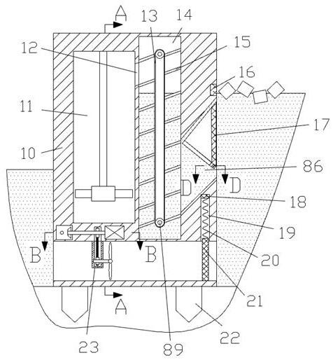
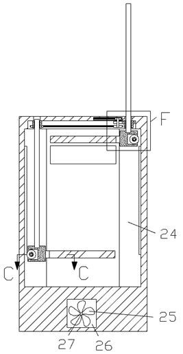
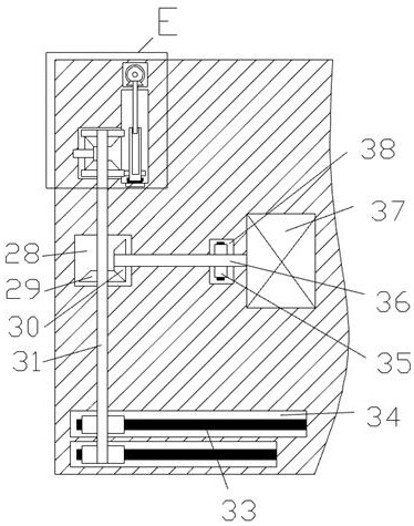
[0023] Such as Figure 1-7As shown, a river hydroelectric power generation device with a garbage collection and compression function of the device of the present invention includes a main body box 10, the lower end surface of the main body box 10 is fixedly connected with a fixed pile 22, and the left and right through holes are arranged in the main body box 10. The power generation chamber 26, the upper side of the power generation chamber 26 is provided with a conveying chamber 14, the right side of the...


PUM


Abstract

The invention discloses a river hydroelectric power generation device with a garbage collection and compression function; it comprises a main body box, the lower end surface of the main body box is fixedly connected with a fixed pile, the main body box is provided with a power generation chamber penetrating from left to right, and a conveying chamber is arranged on the upper side of the power generation chamber. The right side of the conveying chamber is connected with a filter frame chamber, and the upper end of the left end surface of the conveying chamber is connected to the left with a garbage through chamber, and the water flow is blocked by the baffle, so that the garbage on the water surface is collected by the water flow and at the same time, the water on the right side of the baffle is accumulated. Potential energy, so as to increase the flow rate of the water flow after opening the baffle to meet the power generation requirements. At the same time, the water level drops and the triangular collection filter frame completes the collection and dry separation of garbage to prevent the garbage from being soaked in water for a long time. It is transported through the conveying filter plate When the garbage enters the compression chamber, the compression plate is used to complete the compression of the garbage and limit its rebound, so as to facilitate subsequent transportation and utilization.

Description

technical field [0001] The invention relates to the relevant technical field of hydroelectric power generation equipment, in particular to a river hydroelectric power generation device with garbage collection and compression functions. Background technique [0002] The current hydropower generation is usually based on rivers and lakes. Since small rivers usually have a small water flow, it is difficult to generate electricity. Therefore, the utilization of water resources in small flowing rivers has yet to be developed. On the other hand, most of these small rivers There are all kinds of garbage floating, and there is a possibility that the garbage will be stirred into the fan blades and damage the generator during the power generation process. At the same time, most of the garbage in the river is salvaged manually, which is inefficient, and the garbage floating on the water surface is relatively small in density and large in size. After collection and salvage, the volume is...

Claims


Application Information

Patent Timeline
Patent Type & Authority Patents(China)
IPC IPC(8): B30B9/30B30B15/30E02B15/10F03B13/00
CPCB30B9/3003B30B9/301E02B15/10F03B13/00F05B2220/706Y02P70/10
Inventor 高上犁
Owner 南京溧水高新产业股权投资有限公司
Learn More