Eureka AIR delivers breakthrough ideas for toughest innovation challenges, trusted by R&D personnel around the world.

Rated pressure compression roller device

A technology of rated pressure and pressure roller, which is applied in the direction of transportation and packaging, winding strips, sending objects, etc., can solve the problems of inaccurate test results, low test efficiency, uneven force on test pieces, etc., to save consumption , Guaranteed stability, easy and fast operation

Pending Publication Date: 2020-09-01
SHANGHAI XINAN CAR DEADENING FELT
View PDF0 Cites 0 Cited by
  • Summary
  • Abstract
  • Description
  • Claims
  • Application Information

AI Technical Summary

Problems solved by technology

[0003] The currently used elastic pressure roller or manual roller, even if the minimum force that can be set meets the test requirements, there will be people applying extra pressure on the roller during use, resulting in uneven or excessive force on the test piece, resulting in subsequent tests inaccurate result
[0004] Although the relevant prior art discloses a large-scale electric pressing roller equipment, which can perform uniform pressing, but this equipment needs to clamp the test piece and the test plate to avoid the influence of manpower, and the test efficiency is low

Method used


Image

  • Rated pressure compression roller device
  • Rated pressure compression roller device
  • Rated pressure compression roller device

Examples


Embodiment Construction

[0027] The present invention will be described in detail below with reference to the drawings and specific embodiments. This embodiment is implemented on the premise of the technical solution of the present invention, and provides detailed implementation and specific operation procedures, but the protection scope of the present invention is not limited to the following embodiments.

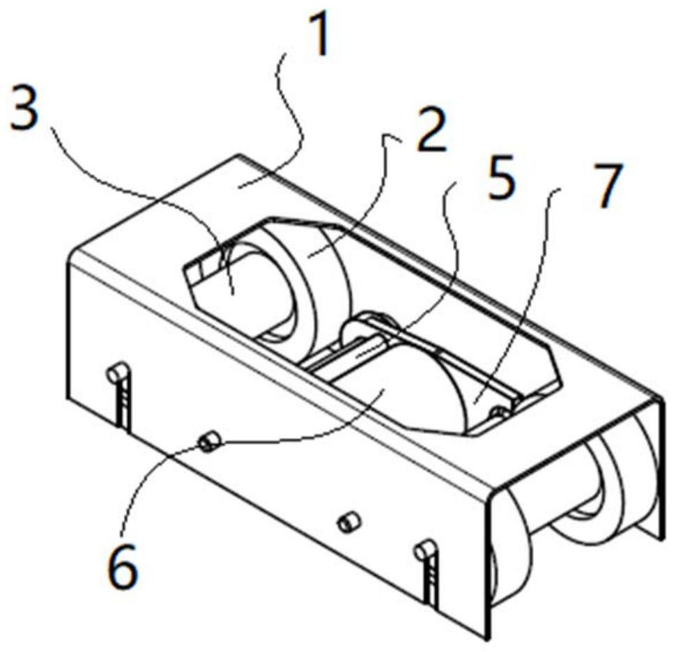
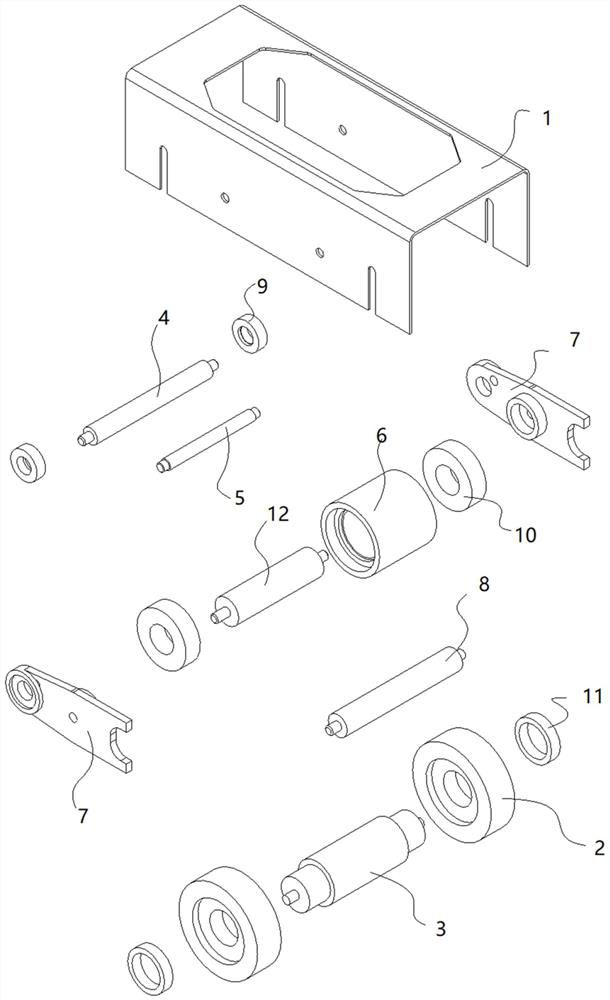
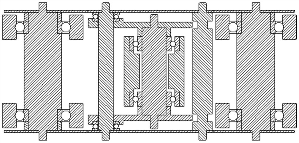
[0028] A pressure roller device with rated pressure, such as Figure 1 to Figure 4 As shown, it includes a housing 1 and a roller module for guiding and a roller module arranged in the housing 1. There are two roller modules in total. The roller module is located between the two roller modules. The roller module includes a roller 6 and a pendulum. The arm limit shaft 8 and the two swing arms 7, the swing arm limit shaft 8 is fixed in the housing 1, one end of the two swing arms 7 is connected by the swing arm shaft 4, and the other end is provided with a groove, the swing arm limit The two ends of t...


PUM


Abstract

The invention relates to a rated pressure compression roller device. The device comprises a shell, two compression roller modules and two roller modules for guide, wherein the compression roller modules and the roller modules for guide are arranged in the shell, two roller modules are arranged, and the compression roller modules are located between the two roller modules; and each compression roller module comprises a compression roller, a swing arm limiting shaft and two swing arms, wherein the swing arm limiting shafts are fixed inside the shell, one ends of each two swing arms are connected through a swing arm shaft, grooves are formed in the other ends of each two swing arms, the two ends of each swing arm limiting shaft are located in the grooves in each two swing arms correspondingly, the two ends of each compression roller are rotationally connected with each two swing arms correspondingly, the compression rollers are located between the swing arm limiting shafts and the swingarm shafts, and swing arm thrust bearings are arranged between the swing arm shafts and the swing arms. Compared with the prior art, the compression rollers are fixed to the shell in a flexible suspension mode so that acting force with rated magnitude can be output, and the situation that in the working process, a person applies extra pressure to the rollers, so that a test piece is unevenly or excessively stressed can be avoided.

Description

Technical field [0001] The invention relates to a roller device, in particular to a rated pressure pressing roller device. Background technique [0002] When testing the adhesive quality (peeling force, stickiness) between the tape or aluminum foil and the component, in order to obtain accurate test data, it is necessary to keep the test piece fully adhered to the test board. In the prior art, a roller is generally used The wheel enables the test piece to be completely adhered to the test board before proceeding to the next test. [0003] The elastic pressure roller or manual roller currently in use, even if the minimum force that can be set meets the test requirements, there will be people applying extra pressure on the roller during use, resulting in uneven or excessive force on the test piece, resulting in subsequent tests The result is not accurate. [0004] Although the related prior art discloses a large-scale electric pressing roller device that can perform uniform pressing,...

Claims


Application Information

Patent Timeline
Patent Type & Authority Applications(China)
IPC IPC(8): B65H37/04B65H20/02
CPCB65H37/04B65H20/02
Inventor 万一
Owner SHANGHAI XINAN CAR DEADENING FELT
Why Eureka
Eureka Blog
Learn More