Wind power boosting device

A technology of boosting and wind power, applied in the directions of wind turbines, wind-driven propulsion components, and wind turbine combinations, etc., can solve the problems of large alternating load on the main shaft of the turntable, reduce the service life of the main shaft, increase maintenance costs, etc., and avoid alternating effect of load, extended service life and reduced maintenance costs

Pending Publication Date: 2020-09-01
CSIC SHANGHAI MARINE ENERGY SAVING TECH DEV CO LTD
View PDF0 Cites 2 Cited by
  • Summary
  • Abstract
  • Description
  • Claims
  • Application Information

AI Technical Summary

Problems solved by technology

[0003] In the harsh marine environment, the ship will produce large roll and pitch during the operation, which will cause the outer cylinder to shake, which may cause the eccentricity of the turntable, resulting in a large alternation of the main axis where the turntable is located. load, thereby reducing the service life of the spindle and increasing maintenance costs

Method used


Image

  • Wind power boosting device
  • Wind power boosting device
  • Wind power boosting device

Examples


Embodiment Construction

[0028] In order to make the technical problems solved by the present invention, the technical solutions adopted and the technical effects achieved clearer, the technical solutions of the present invention will be further described below in conjunction with the accompanying drawings and through specific implementation methods. It should be understood that the specific embodiments described here are only used to explain the present invention, but not to limit the present invention. In addition, it should be noted that, for the convenience of description, only the parts related to the present invention are shown in the drawings but not all of them.

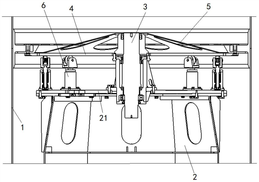
[0029] Such as figure 1 As shown, this embodiment provides a wind boosting device, which is applied to ships. The wind power booster includes an outer cylinder 1 capable of rotating around its own axis and an inner tower 2, a turntable 4 and a main shaft 3 arranged therein. The inner tower 2 is rotatably connected with the inner to...


PUM


Abstract

The invention relates to the technical field of ships, and discloses a wind power boosting device. The wind power boosting device comprises an outer cylinder which can rotate around own axis, and further comprises an inner tower, a rotary table and a main shaft which are arranged in the outer cylinder, the lower end of the main shaft extends into the inner tower and is rotatably connected with theinner tower, and the upper end of the main shaft is connected with the outer cylinder through the rotary table; and the wind power boosting device further comprises a plurality of auxiliary supporting assemblies which are arranged between a cover plate at the top of the inner tower and the rotary table and distributed in the circumferential direction of the main shaft, one ends of the auxiliary supporting assemblies are correspondingly connected with one of the cover plate at the top of the inner tower and the rotary table, and the other ends of the auxiliary supporting assemblies are correspondingly connected with the other one in a rolling mode. According to the wind power boosting device, the rotary table is supported by the multiple auxiliary supporting assemblies to bear the transverse force in each direction during the rotation of the outer cylinder, the stability in the rotation process of the outer cylinder is ensured, thus the shaking of the outer cylinder is reduced, the main shaft is prevented from producing large alternating load, and the service life of the main shaft is prolonged; and meanwhile the auxiliary supporting assemblies are connected with the rotary table or the cover plate at the top of the inner tower in a rolling mode, the rotational inertia cannot be increased, and thus the energy consumption can also not be increased.

Description

technical field [0001] The invention relates to the technical field of ships, in particular to a wind boosting device. Background technique [0002] The wind boosting device is mainly used on ships, and it includes a rotor, a main shaft and an outer cylinder that rotate together. The outer cylinder has a large size and a high linear speed, and it is easy to generate alternating loads with the main shaft. Therefore, when the rotor rotates, the stability of the outer cylinder is required to be higher. [0003] In the harsh marine environment, the ship will produce large roll and pitch during the operation, which will cause the outer cylinder to shake, which may cause the eccentricity of the turntable, resulting in a large alternation of the main axis where the turntable is located. The load acts, thereby reducing the service life of the spindle and increasing maintenance costs. Contents of the invention [0004] The purpose of the present invention is to provide a wind boo...

Claims


Application Information

Patent Timeline
Patent Type & Authority Applications(China)
IPC IPC(8): F03D9/32F03D80/00B63H9/00
CPCF03D9/32F03D80/00B63H9/00Y02E10/72Y02E10/728
Inventor 郭峰山朱玉柱黄振宇吴幼华孙承灿
Owner CSIC SHANGHAI MARINE ENERGY SAVING TECH DEV CO LTD
Why Eureka
Try Eureka