
Blasting type pressure relief device with spring actuator

A pressure relief device and actuator technology, applied in the direction of valve heating/cooling device, valve device, function valve type, etc., can solve the problem that the device cannot realize the function, etc., and achieve easy observation, low downtime cost and high reliability Effect

Pending Publication Date: 2020-09-01
BEIJING AEROSPACE PETROCHEM TECH & EQUIP ENG CORP LTD
View PDF0 Cites 1 Cited by
  • Summary
  • Abstract
  • Description
  • Claims
  • Application Information

AI Technical Summary

Problems solved by technology

[0010] However, due to its structural principles and characteristics, this blasting type pressure relief device needs the help of on-site instrument air conditions, which brings some inconvenience to on-site installation. If there is no instrument air on site, the device cannot realize its function.

Method used


Image

  • Blasting type pressure relief device with spring actuator
  • Blasting type pressure relief device with spring actuator
  • Blasting type pressure relief device with spring actuator

Examples


Embodiment Construction

[0051]The technical solution of the present invention will be described in detail below in conjunction with the accompanying drawings and specific embodiments.

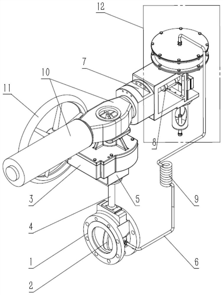
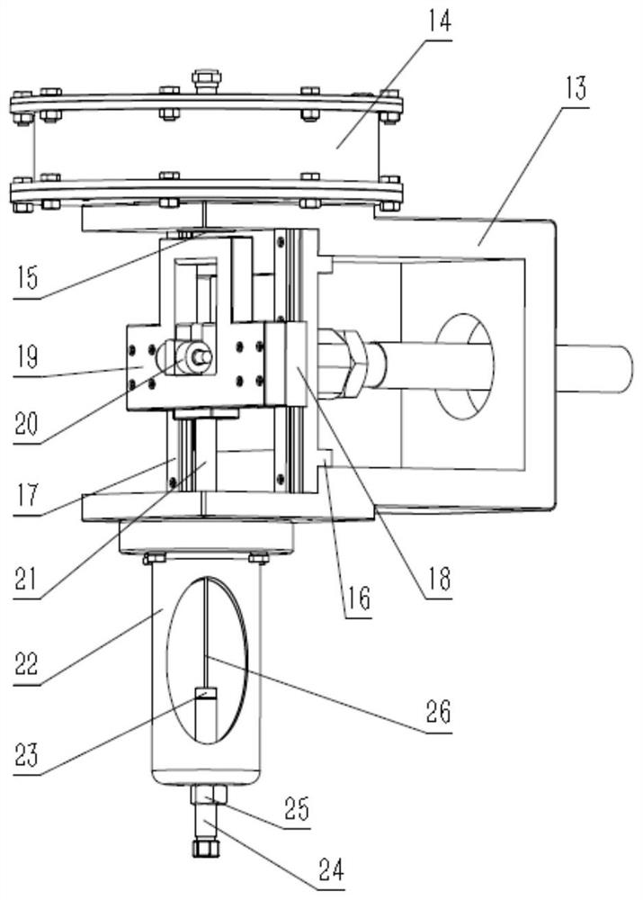
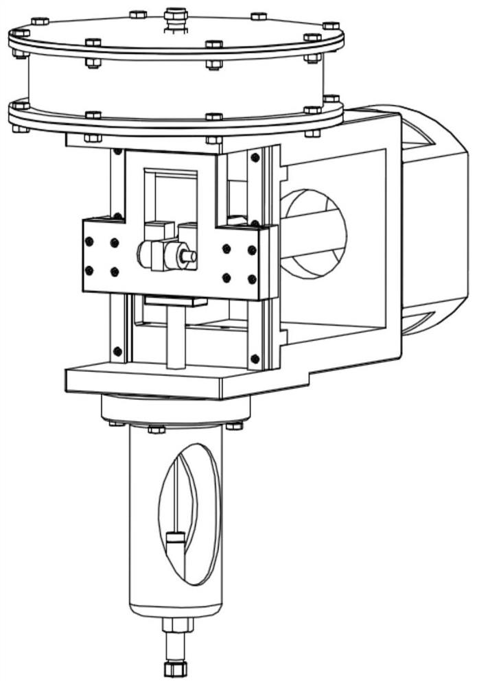
[0052] Such as Figure 1~6 As shown, the present invention is a blasting type pressure relief device with a spring actuator, the pressure relief device is composed of a pilot valve, a main valve, a spring actuator 10, a heat exchange tube 9 and a connecting pipeline;

[0053] The main valve, the pilot valve, and the spring actuator 10 are connected together through the bracket 5;

[0054] Through the pressure introduction pipe 6, the medium upstream of the main valve enters the cylinder 14 in the pilot valve through the heat exchange pipe 9, and through the structure of the heat exchange pipe 9, the temperature of the working medium is adjusted to normal temperature through natural convection heat exchange, so as to ensure that the pressure relief device can operate Good sealing is achieved under severe working condi...


PUM


Abstract

The invention belongs to the technical field of overpressure protection devices, and particularly relates to a blasting type pressure relief device with a spring actuator. The pressure relief device consists of a pilot valve, a main valve, a spring actuator body, a heat exchange tube and a connecting pipeline. The pressure relief device is compact in overall structure; the main valve adopts a metal seal; and an upstream medium enters the pilot valve through the heat exchange tube to ensure that a pressure relief triggering mechanism and a sealing mechanism have higher reliability under harsh working conditions of ultra-low temperature and high temperature. When pipeline pressure rises to set opening pressure, the pilot valve is opened and drives the main valve to be quickly opened throughthe spring actuator body, so that safe and accurate relief is realized. Besides, the pressure relief state is easy to observe, the maintenance workload is less and the downtime cost is low; and the blasting type pressure relief device has higher precision and can replace conventional safety valve and rupture disk in specific occasions.

Description

technical field [0001] The invention belongs to the technical field of overpressure protection devices, and in particular relates to a burst pressure relief device with a spring actuator. Background technique [0002] With the increasing requirements of environmental protection, the oil refining, chemical industry, LNG and other industries are gradually replacing elevated flares with ground flares. The ground flare system has a strong potential demand for blasting pressure relief devices. [0003] There are three common types of blasting pressure relief devices: [0004] The first is a pressure rod type blasting pressure relief device similar to the spring direct load type safety valve structure. The medium pressure directly acts on the blasting needle through the piston valve disc and valve stem. When the system pressure reaches the pressure relief set value, the blasting needle will be unstable, and the disc and seat will be separated instantly to realize accurate and rap...

Claims


Application Information

Patent Timeline
Patent Type & Authority Applications(China)
IPC IPC(8): F16K17/06F16K17/10F16K37/00F16K49/00
CPCF16K17/06F16K17/10F16K49/00F16K37/0008F16K37/0083F16K37/0091
Inventor 马静周浩岳大皓范军唐旭丽仝一然苏斌
Owner BEIJING AEROSPACE PETROCHEM TECH & EQUIP ENG CORP LTD
Learn More