
Hydropower cluster sending-out net rack optimization method considering clean energy utilization rate

A technology of clean energy and grid optimization, applied in the field of power grid

Active Publication Date: 2020-09-01
国家电网公司西南分部
View PDF4 Cites 0 Cited by
  • Summary
  • Abstract
  • Description
  • Claims
  • Application Information

AI Technical Summary

Problems solved by technology

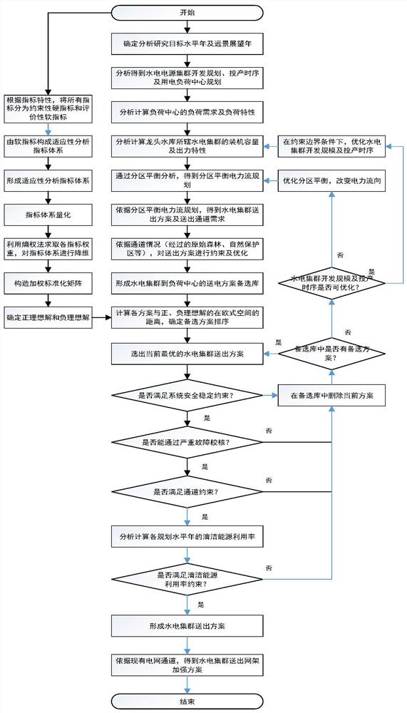
[0025] The purpose of the present invention is to: provide a hydropower cluster sending network frame optimization method considering the utilization rate of clean energy, solve the long-term problem of the construction of the outgoing network frame under the background of the construction and development process of the leading reservoir, and establish a corresponding regional power balance According to the construction and operation of transmission channels, the development planning of hydropower station clusters and the timing of commissioning, the mathematical model is optimized, and the greedy algorithm is used to solve the corresponding power transmission alternatives, and finally the evaluation method of entropy weight method is used to evaluate each Evaluate the alternatives, and select the optimal solution for hydropower cluster transmission and related grid construction

Method used


Image

  • Hydropower cluster sending-out net rack optimization method considering clean energy utilization rate
  • Hydropower cluster sending-out net rack optimization method considering clean energy utilization rate
  • Hydropower cluster sending-out net rack optimization method considering clean energy utilization rate

Examples


Embodiment 1

[0125] The preferred embodiment of the present invention provides a hydropower cluster sending grid optimization method that considers the utilization rate of clean energy. Taking the test system of IEEE39 nodes as an example, the network topology diagram is as follows Figure 4 shown.

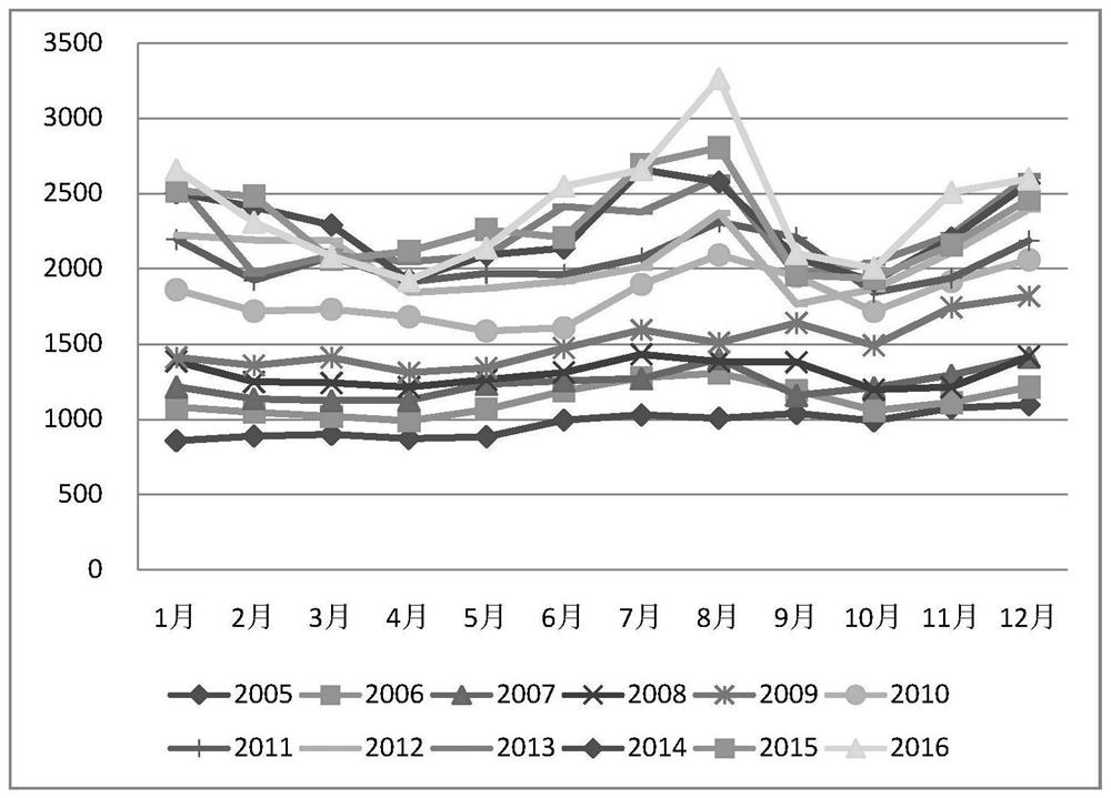
[0126] The data of the actual cascade hydropower stations in a certain river basin are connected to BUS-33, BUS-34, BUS-35, BUS-36, BUS-37, BUS-38 and BUS-39 respectively, and the wind power cluster is connected as a renewable energy Entering BUS-30, the monthly output and installed capacity of the cascade hydropower station in a certain year are shown in Table 1 - the installed capacity and output parameters of the cascade hydropower station.

[0127] Table 1 (unit: MW)

[0128]

[0129] Due to the limitation of the channel capacity, the electric energy generated by the wind power cluster may not be completely absorbed by the grid, and there is an abandoned air volume. Therefore, this emb...


PUM


Abstract

The invention discloses a hydropower cluster sending-out net rack optimization method considering a clean energy utilization rate, and the method comprises the steps: calculating the membership degreeof an evaluation set to which each scheme belongs, and determining the sorting of alternative schemes; and S17, selecting a current optimal hydropower cluster sending-out scheme; S18, judging whethersystem safety and stability constraints are met or not; S19, judging whether severe fault checking can be passed or not; S20, judging whether channel constraints are satisfied; S21, deleting the current scheme from the alternative library; S22, judging whether an alternative scheme exists in the alternative library or not; s23, judging whether the hydropower cluster development scale and the commissioning time sequence can be optimized or not; and S24, under the constraint boundary condition, optimizing the hydropower cluster development scale and the commissioning time sequence; S25, optimizing partition balance, and changing the power flow direction; S26, analyzing and calculating the clean energy utilization rate of each planning level year; s27, judging whether the clean energy utilization rate constraint is met or not; s28, forming a hydropower cluster sending-out scheme; and S29, according to the existing power grid channel, obtaining a hydropower cluster sending-out grid frameoptimization scheme.

Description

technical field [0001] The invention belongs to the field of power grids, and relates to a method for optimizing a hydropower cluster sending network frame considering the utilization rate of clean energy. Background technique [0002] At present, domestic research on cascade hydropower has been initially carried out, but the research mainly focuses on various coordination and optimization scheduling methods during the operation of cascade hydropower. [0003] Patent [1] proposes a cascade hydropower "virtual pumped-storage power station" scheduling method, with the minimum deviation between the actual and target peak-shaving power and the minimum water consumption of the cascade hydropower as the scheduling objectives, and constructs a cascade hydropower "virtual pumped-storage power station" scheduling The objective function is used to solve the optimal dispatching in order to realize the short-term dispatching plan of the power system; [0004] Patent [2] discloses an ad...

Claims


Application Information

Patent Timeline
IPC IPC(8): G06Q10/04G06Q10/06G06Q50/06
CPCG06Q10/04G06Q10/06393G06Q50/06Y02E40/70Y04S10/50
Inventor 路亮魏明奎周泓黄媛
Owner 国家电网公司西南分部
Learn More