Telescopic mobile terminal

A mobile terminal and telescopic technology, which is applied to the telephone structure, telephone communication, electrical components, etc., can solve the problems of reducing the service life of the mobile terminal, breaking the arc shrapnel 222, reducing the diversity of user experience, etc., so as to shorten the maintenance time. , the effect of prolonging the service life and improving the maintenance efficiency

Inactive Publication Date: 2020-09-01
贺晓芳
1 Cites 0 Cited by

AI-Extracted Technical Summary

Problems solved by technology

[0004] However, although this mobile terminal can extend the functional components from the housing, it still has the following defects: 1. When the user presses the first driver 223 and the second driver 224 at the same time, if the force is too large, it will cause an arc. Shaped shrapnel 222 is broken, thereby reducing the service life of the mobile terminal
II. After the user extends the functional components from the housing, the user still needs to hold the first driver 223 and the second driver 224 to prevent the arc-shaped shrapnel 222 from resetting, which will undoubtedly cause the use...

Abstract

The invention discloses a telescopic mobile terminal. An executing mechanism used for driving the functional assembly to do linear motion is further arranged in the cavity; the executing mechanism comprises a driving shaft, a torsional spring and a first groove formed in the bottom of the shell. The driving shaft comprises a rotating shaft and a square head which are fixedly arranged in sequence from top to bottom; a cam is installed at the top end of the rotating shaft, a pin A is fixedly arranged at the top of a protruding part of the cam, a first connecting rod is hinged to the pin A, a pinB is fixedly arranged on the bottom surface of the other end of the first connecting rod, a second connecting rod is hinged to the pin B, the other end of the second connecting rod is hinged to the functional assembly, and the rotating shaft is sleeved with a torsional spring. The executing mechanism further comprises an iron block and a magnet; the iron block and the magnet are both arranged inthe first groove, the iron block is fixedly arranged at the right end of the square head, and the magnet is fixedly arranged on the left side wall of the first groove. The beneficial effects of the invention are that the structure is compact, the manufacturing cost is low, the service life is long, the maintenance of functional devices is facilitated, and the diversity of user experience is improved.

Application Domain

Technology Topic

Left lateral wallCam +3

Image

  • Telescopic mobile terminal
  • Telescopic mobile terminal
  • Telescopic mobile terminal

Examples

  • Experimental program(1)

Example Embodiment

[0031] The present invention will be further described below in conjunction with the accompanying drawings. The protection scope of the present invention is not limited to the following:
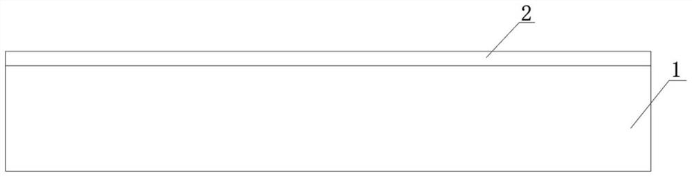
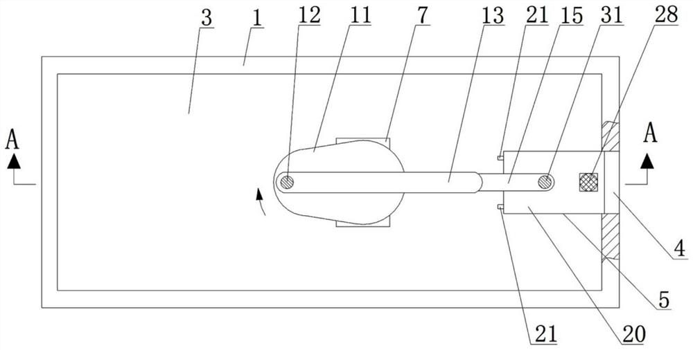
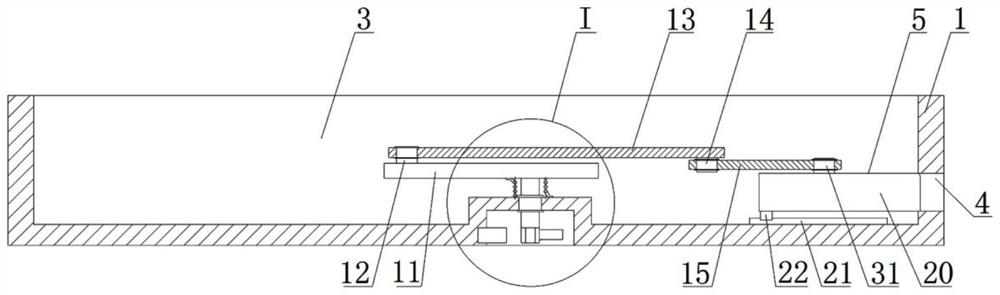
[0032] Such as Figure 1~7 As shown, a telescopic mobile terminal includes a casing 1 and a display screen 2. The display screen 2 is fixed on the top of the casing 1, and a cavity 3 is enclosed between the display screen 2 and the casing 1. A guide groove 4 is opened on the right end surface of the housing 1, and the guide groove 4 is in communication with the cavity 3. The cavity 3 is provided with a functional component 5 that can pass through the guide groove 4, and the cavity 3 is also An actuator for driving the functional assembly 5 to move linearly is provided. The actuator includes a drive shaft, a torsion spring 6 and a first groove 7 opened at the bottom of the housing 1. The drive shaft includes a sequence from top to bottom. A fixed rotating shaft 8 and a square head 9, the drive shaft and the threaded rod 26 are both vertically arranged, the square head 9 is a hexagonal head, the rotating shaft 8 is arranged through the bottom surface of the first groove 7, and the cylindrical surface of the rotating shaft 8 Two snap rings 10 are fixed on the top, one snap ring 10 is supported on the bottom surface of the inner cavity of the housing 1, the other snap ring 10 is in contact with the bottom surface of the first groove 7, and the square head 9 is set in the first recess. In the groove 7, a cam 11 is installed at the top of the rotating shaft 8, a pin A12 is fixed on the top of the convex portion of the cam 11, a first link 13 is hinged on the pin A12, and the other end of the first link 13 is on the bottom surface The pin B14 is fixedly provided with a second connecting rod 15 hinged on the pin B14, and the other end of the second connecting rod 15 is hingedly connected to the functional assembly 5. In this embodiment, the top of the sliding seat 20 is fixedly provided with a pin C31, The other end of the second link 15 is hinged on the pin C31. Such as Figure 3~4 As shown, the torsion spring 6 is sleeved on the rotating shaft 8, the lower leg 16 of the torsion spring 6 is fixed on the bottom surface of the inner cavity of the housing 1, and the upper leg 17 of the torsion spring 6 is fixed on the bottom surface of the cam 11. on.
[0033] The actuator also includes an iron block 18 and an iron absorption stone 19. The iron block 18 and the iron absorption stone 19 are both arranged in the first groove 7. The iron block 18 is fixed at the right end of the square head 9, and the iron absorption stone 19 is fixed in the first recess. On the left side wall of the groove 7, in this embodiment, the side wall of the first groove 7 is provided with a clamping groove 30, one end of the iron magnet 19 is embedded in the clamping groove 30, and the other end extends into the first groove Within 7.
[0034] Such as Figure 2~3 As shown, the functional assembly 5 includes a sliding seat 20 and a guide rail 21, the guide rail 21 is fixed on the bottom surface of the inner cavity of the housing 1, the guide rail 21 is arranged opposite to the guide groove 4, and the bottom of the sliding seat 20 A sliding block 22 is fixedly arranged, and the sliding block 22 is slidably mounted on the guide rail 21. One end of the sliding seat 20 extends into the guide groove 4, and the top of the sliding seat 20 is provided with a groove body 23. Two guide rails 21 are fixedly arranged on the bottom surface of the cavity of the housing 1, and the two guide rails 21 are arranged horizontally. The bottom of the sliding seat 20 is fixedly provided with two sliding blocks 22, and the two sliding blocks 22 slide separately Installed on the guide rail 21.
[0035] Such as Figure 2~7 As shown, the bottom of the sliding seat 20 is provided with a second groove 24, the bottom of the second groove 24 is fixedly provided with a nut 25, the nut 25 is threaded with a threaded rod 26, and the upper end of the threaded rod 26 penetrates The bottom of the second groove 24 extends into the inner cavity of the sliding seat 20, the top of the threaded rod 26 is fixedly provided with a mounting plate 27, the mounting plate 27 is located directly below the groove body 23, and the top of the mounting plate 27 is fixedly provided with The functional device 28 that can penetrate the trough 23, the functional device 28 is any one of a camera module, an iris recognition module, a face recognition module, a fingerprint recognition module, a flash, a photosensitive sensor, a receiver, and a microphone, The lower end of the threaded rod 26 extends into the second groove 24, and the bottom of the threaded rod 26 is fixedly provided with a knob 29, and the threaded rod 26 can move up or down linearly by turning the knob 29 forward and backward.
[0036] The working process of the present invention is as follows:
[0037] When the user wants to use the functional device 28 in the functional assembly 5 in the mobile terminal, the user turns the square head 9 back with his finger, so that the square head 9 rotates around the axis of the drive shaft from back to front. Direction as Figure 4 As shown by the middle arrow, the square head 9 drives the rotating shaft 8 to rotate, and the rotating shaft 8 drives the cam 11 to rotate around the axis of the drive shaft. The rotation direction of the cam 11 is as follows figure 2 As shown by the middle arrow, the cam 11 drives the pin A12 and pulls the upper leg 16 of the torsion spring 6 to rotate. The torsion spring 6 is twisted and deformed. At the same time, the pin A12 drives the first link 13 to rotate, and the first link 13 drives the second link via the pin B14. The rod 15 rotates, and the second connecting rod 15 transmits the torque to the pin C31. The pin C31 drives the sliding seat 20 to move linearly to the right along the guide rail 21, and then the sliding seat 20 passes through the guide groove 4 and extends to the cavity 3 Externally, the extension of functional components is realized. When the iron block 18 rotates to touch the magnet 19 Figure 8 As shown, the square head 9 can no longer be rotated, and the functional assembly 5 no longer protrudes as Picture 9 As shown, at this time, the user can use the functional device, which realizes providing the user with a diverse experience. When the functional assembly 5 is to be retracted, the square head 9 can be reversely rotated to separate the iron block 18 from the magnet 19, and then the square head 9 is loosened. At this time, the cam 11 moves around the drive shaft under the restoring force of the torsion spring 6 The axis is reversed. The cam 11 drives the first link 13 to reverse, the first link 13 drives the second link 15 to reverse, and the second link 15 drives the sliding seat 20 along the guide rail 21 through the guide groove 4 and enters Into the cavity 3, thereby realizing the retracting of the functional components such as figure 2 Shown.
[0038] When the functional assembly 5 extends outward, the iron block 18 is adsorbed on the iron magnet 19, so that the sliding seat 20 can no longer move, so there is no need for the user to hold the square head 9 again, thus ensuring that the user has an idle hand to operate the display screen Or functional device 28, the mobile terminal not only facilitates user operations, but also improves the diversity of user experience. In addition, the mobile terminal also replaces the original use of bending springs to achieve the extension or retraction of the functional components, but uses the method of rotating the square head 9 to achieve the extension or retraction of the functional components, without damaging parts. This greatly extends the service life of the mobile terminal.
[0039] When the functional device 28 needs to be repaired, the worker only needs to extend the functional component 5 to the outside of the cavity 3, and then turn the knob 29. The knob 29 drives the threaded rod 26 to rotate, and the threaded rod 26 moves upward in a straight line, and then the functional device 28 passes upward through the trough body 23 and extends to the outside of the sliding seat 20 as Picture 10 As shown, at this time, the maintenance personnel can repair the functional device 28 externally. Compared with the traditional maintenance inside the sliding seat, the operation space during maintenance is increased, which not only facilitates the maintenance personnel to repair the functional device, but also shortens Maintenance time improves maintenance efficiency.
[0040] The above are only the preferred embodiments of the present invention. It should be understood that the present invention is not limited to the form disclosed herein, and should not be regarded as an exclusion of other embodiments, but can be used in various other combinations, modifications and environments, and It can be modified through the above teaching or technology or knowledge in related fields within the scope of the concept described herein. However, modifications and changes made by those skilled in the art do not depart from the spirit and scope of the present invention, and should fall within the protection scope of the appended claims of the present invention.

PUM

no PUM

Description & Claims & Application Information

We can also present the details of the Description, Claims and Application information to help users get a comprehensive understanding of the technical details of the patent, such as background art, summary of invention, brief description of drawings, description of embodiments, and other original content. On the other hand, users can also determine the specific scope of protection of the technology through the list of claims; as well as understand the changes in the life cycle of the technology with the presentation of the patent timeline. Login to view more.

Similar technology patents

Classification and recommendation of technical efficacy words

  • Extended service life
  • Large operating space

Large-size multi-axis-linkage electrolytic machine tool

ActiveCN103464845ALarge operating spaceEasy to install and adjustMachining working media supply/regenerationElectric circuitsMachine toolPulse power supply
Owner:NANJING UNIV OF AERONAUTICS & ASTRONAUTICS
Why Eureka
Try Eureka