
Device and method for projecting an image

一种投影图像、设备的技术,应用在图像投影的设备领域

Inactive Publication Date: 2020-09-01
ROBERT BOSCH GMBH
View PDF4 Cites 0 Cited by
  • Summary
  • Abstract
  • Description
  • Claims
  • Application Information

AI Technical Summary

Problems solved by technology

When the eye is directed onto the scanning unit, the maximum limit is derived

Method used


Image

  • Device and method for projecting an image
  • Device and method for projecting an image
  • Device and method for projecting an image

Examples


Embodiment Construction

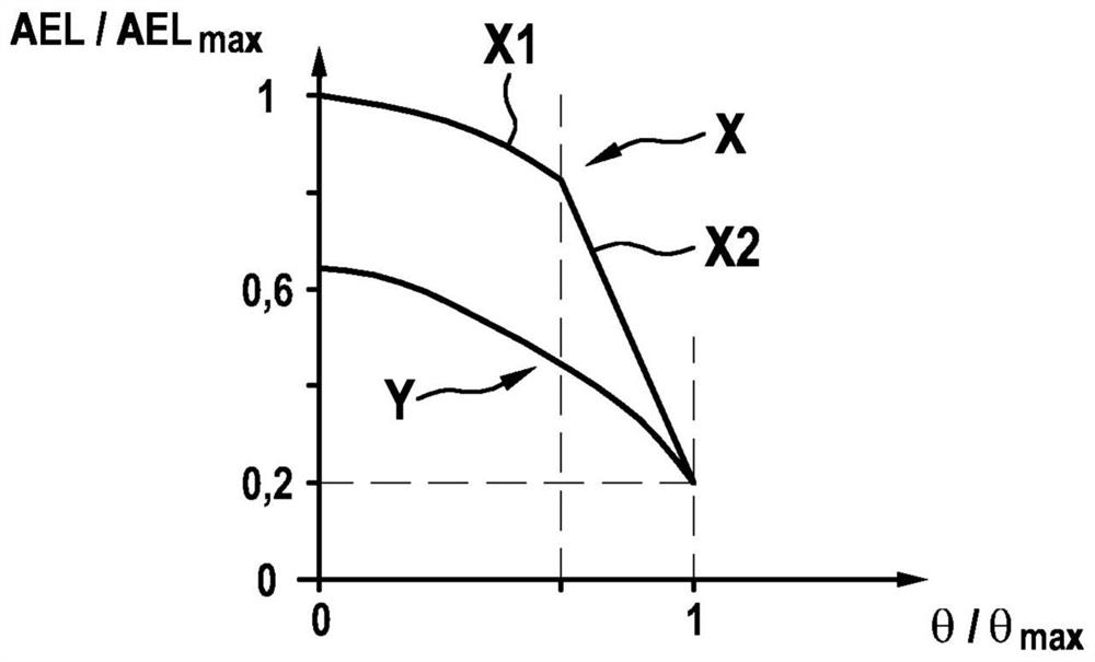
[0035] In the following, it will first be explained why the edge region of the solid angle region scanned by means of the laser light deflected by the micromirror is particularly dangerous for the human eye.

[0036] For this, in figure 1 In , the allowable energy limit (AEL) is constructed as a function of the scanning angle θ of the micromirror around the fast axis, where the two parameters are normalized to one. The permissible energy limit is determined for the selected laser category according to the maximum permissible exposure (English maximum permissible exposure, MPE for short).

[0037] As can be seen with respect to the first curve X, an essentially sinusoidal curve X1 of the permissible energy limit is shown for small scan angles θ (ie in the vicinity of the center of the scanned solid angle range). Here, the limitation of the permissible energy limit essentially results from the above-mentioned first criterion—that is, a simple scan of the eye. For larger scan a...


PUM


Abstract

The invention relates to a device (1a, 1b, 1c) for projecting an image, comprising: a laser device (2) which is designed to emit a laser beam (L), said laser device (2) having a modulating device (21)which is designed to modulate image data onto the laser beam (L); and a micromirror device (3) which is designed to deflect the laser beam (L) in a cell-shaped manner; wherein the modulating device (21) is designed to modulate the laser beam (L) such that a specified optical warning signal is emitted in a region around the reversal points of the cell-shaped deflection.

Description

technical field [0001] The invention relates to a device for image projection and a method for projecting an image. In particular, the invention relates to a laser scanner-projector, for example for a portable device. Background technique [0002] For projecting images, laser scanners with micromirrors can be used, wherein the micromirrors deflect the emitted laser beam. For generating two-dimensional images, for example, micromirrors which can be pivoted about two mutually orthogonal axes can be used. For this purpose, the micromirrors are typically resonantly vibrated at a fast frequency about a first axis, and quasi-statically deflected at a slow frequency about a second axis. As a result, two mutually perpendicular sinusoidal oscillations with different frequencies are superimposed. This results in an essentially line-like movement of the laser beam, wherein a line is scanned during a fast deflection half period, and a frame with a plurality of lines is scanned during...

Claims


Application Information

Patent Timeline
Patent Type & Authority Applications(China)
IPC IPC(8): G02B26/10H04N9/31
CPCG02B26/101H04N9/3135H04N9/3197
Inventor P·奥斯特塔格G·皮拉德
Owner ROBERT BOSCH GMBH
Features
  • Generate Ideas
  • Intellectual Property
  • Life Sciences
  • Materials
  • Tech Scout
  • Unparalleled Data Quality
  • Higher Quality Content
  • 60% Fewer Hallucinations
Learn More