
Robot gripper and robot

A robot hand and robot technology, applied in the field of warehousing and logistics, can solve the problems of damage to the appearance of the grasped object, difficulty in picking up, danger, etc., and achieve the effect of avoiding damage to the appearance of the object and effectively grasping

Pending Publication Date: 2020-09-04
BEIJING JINGDONG SHANGKE INFORMATION TECH CO LTD +1
View PDF13 Cites 0 Cited by
  • Summary
  • Abstract
  • Description
  • Claims
  • Application Information

AI Technical Summary

Problems solved by technology

With the diversification and specialization of the objects picked up by robots, the design of robot grippers is also more complex and rich.
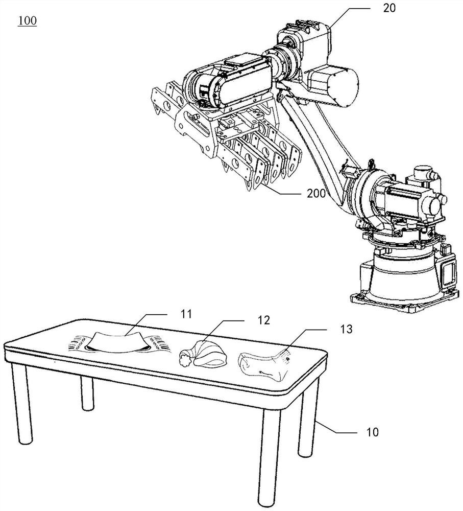
[0003] In the process of realizing the disclosed concept, the inventors have found that there are at least the following problems in the prior art: in the automatic picking of woolen goods (for example: wool socks, felt pads, blankets, wool gloves, etc.) or other soft objects, due to Such items are very difficult to pick up, so the robot gripper cannot be designed in the traditional way. Now the mainstream is a needle-type gripper imported from abroad. The angle (generally 30°) pierces the wool fabric, and the inclined needle is used to bear the weight of the object to be picked up, so as to achieve the purpose of picking up, but this will damage the object to be grabbed by leaving pinholes on the object. Appearance, there may even be a certain danger due to the needles of the claws accidentally falling

Method used


Image

  • Robot gripper and robot
  • Robot gripper and robot
  • Robot gripper and robot

Examples


Embodiment Construction

[0025] Hereinafter, embodiments of the present disclosure will be described with reference to the drawings. It should be understood, however, that these descriptions are exemplary only, and are not intended to limit the scope of the present disclosure. In the following detailed description, for purposes of explanation, numerous specific details are set forth in order to provide a thorough understanding of the embodiments of the present disclosure. It may be evident, however, that one or more embodiments may be practiced without these specific details. Also, in the following description, descriptions of well-known structures and techniques are omitted to avoid unnecessarily obscuring the concept of the present disclosure.

[0026] The terminology used herein is for the purpose of describing particular embodiments only, and is not intended to be limiting of the present disclosure. The terms "comprising", "comprising", etc. used herein indicate the presence of stated features, ...


PUM


Abstract

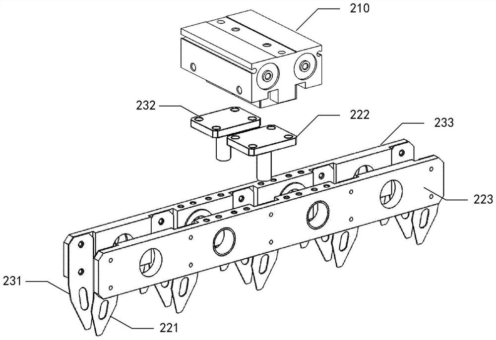
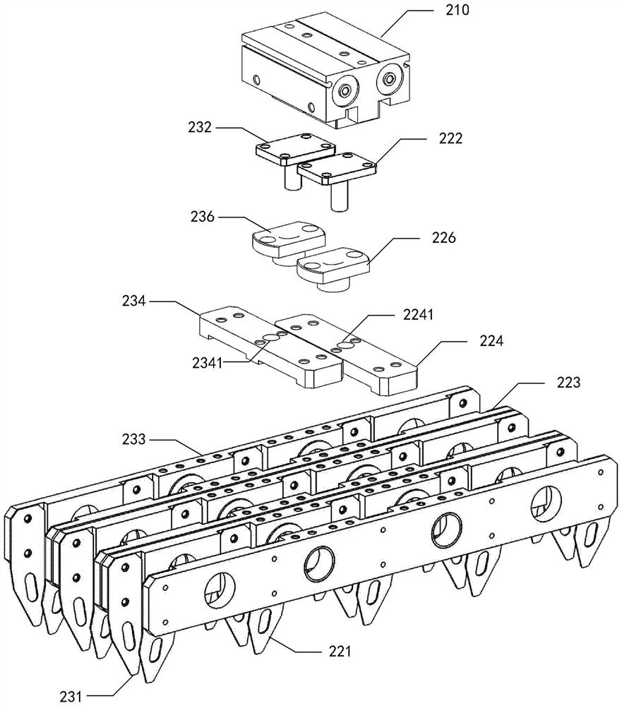
The invention provides a robot gripper and a robot. The robot gripper comprises a drive piece and two clamping mechanisms. The drive piece comprises two output ends capable of moving relatively. One ends of the two clamping mechanisms are connected with the two output ends of the drive piece correspondingly, and the other ends are provided with a sheet first clamping piece and a sheet second clamping piece in an extending manner, wherein the first clamping piece and the second clamping piece are perpendicular to the two output ends. The first clamping piece and the second clamping piece are oppositely arranged. The two clamping mechanisms can move towards or away from each other under driving of the two output ends so that objects can be clamped or thrown through the first clamping piece and the second clamping piece which are oppositely arranged.

Description

technical field [0001] The present disclosure relates to the field of warehousing and logistics, and more specifically, to a robot gripper and a robot. Background technique [0002] With the rapid development of automatic control, communication and computer technology, robots are more and more used in automated production lines, goods inventory and goods picking, and various robot grippers have also emerged as the times require. With the diversification and specialization of the objects picked up by robots, the design of robot grippers has become more complex and rich. [0003] In the process of realizing the disclosed concept, the inventors have found that there are at least the following problems in the prior art: in the automatic picking of woolen goods (for example: wool socks, felt pads, blankets, wool gloves, etc.) or other soft objects, due to Such items are very difficult to pick up, so the robot gripper cannot be designed in the traditional way. Now the mainstream ...

Claims


Application Information

Patent Timeline
IPC IPC(8): B25J15/00B25J15/10
CPCB25J15/00B25J15/10
Inventor 冯宇
Owner BEIJING JINGDONG SHANGKE INFORMATION TECH CO LTD
Learn More