Ceramic tile cement smearing device for building decoration

A ceramic tile and cement technology, applied in the direction of construction and building structure, can solve the problems of uneven application, low work efficiency, large waste of cement, etc., and achieve the effect of convenient use and improved work efficiency.

Active Publication Date: 2020-09-04
安徽贵宏建工集团有限公司
View PDF7 Cites 9 Cited by
  • Summary
  • Abstract
  • Description
  • Claims
  • Application Information

AI Technical Summary

Problems solved by technology

[0005] In order to overcome the shortcomings of low work efficiency, large cement waste, and uneven application when applying cement to tiles, the technical problem of the present invention is to provide a cement that can replace manual application of cement evenly, does not waste cement, and has high work efficiency. Ceramic tile cement applicator for building decoration

Method used


Image

  • Ceramic tile cement smearing device for building decoration
  • Ceramic tile cement smearing device for building decoration
  • Ceramic tile cement smearing device for building decoration

Examples


Embodiment 1

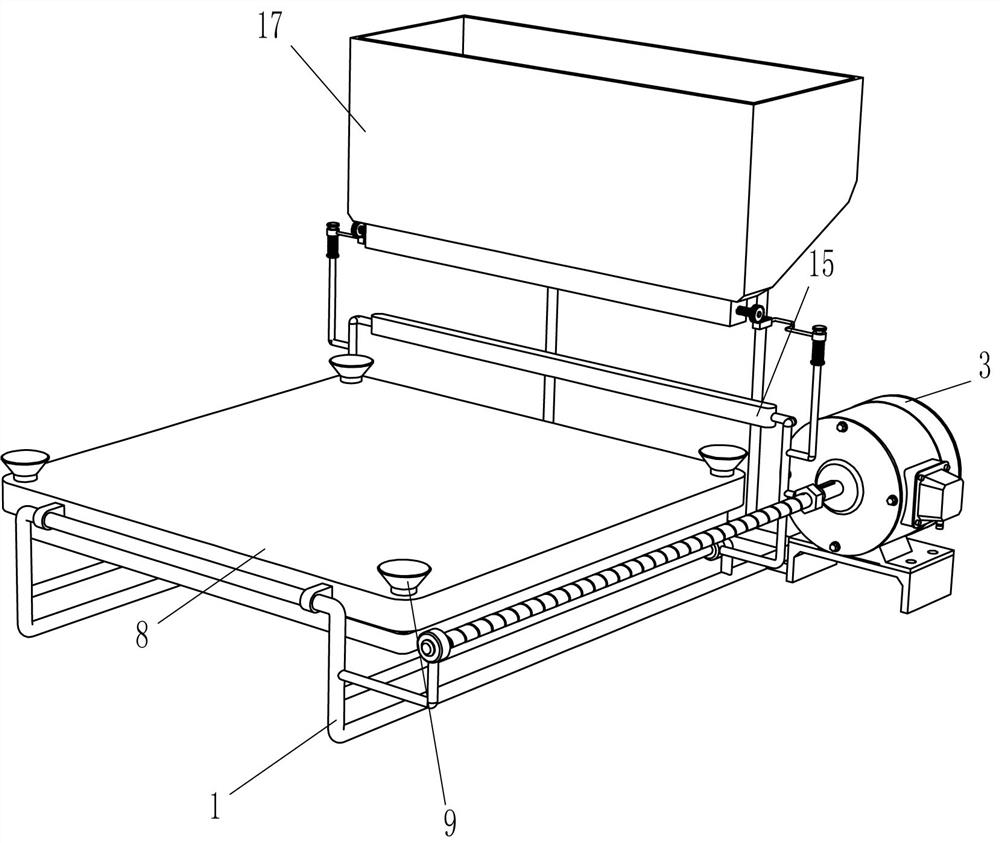
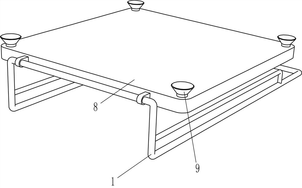
[0021] A kind of ceramic tile cement application device for building decoration, such as Figure 1-6 As shown, it includes a support frame 1, a power assembly, a placement assembly, an air release assembly, and a caressing plate 15. The support frame 1 is provided with a power assembly that provides power by rotating, and the support frame 1 is provided with a placement assembly, placed The assembly is provided with a deflation assembly that deflates by sliding, and a smoothing plate 15 is welded on the power assembly.

[0022] Such as figure 1 , 2 As shown in and 5, the power assembly includes a placement seat 2, a geared motor 3, a right-angle rod 4, a screw mandrel 5, a nut 6 and a connecting rod 7, and the rear right part of the support frame 1 is welded with a placement seat 2, and the placement seat 2 passes through The bolt is fixedly connected with a deceleration motor 3, and the right side of the support frame 1 is symmetrically provided with two right-angled rods 4...

Embodiment 2

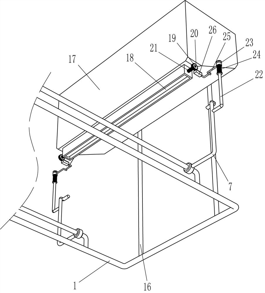
[0030] On the basis of Example 1, such as figure 1 with 6 Shown, also include support rod 16, hopper 17, semi-cylindrical frame 18, rotating rod 19, one-way gear 20, torsion spring 21, guide rod 22, guide sleeve 23, second spring 24, special-shaped rod 25 and tooth Bar 26, bracing frame 1 back side is welded with support bar 16 symmetrically left and right, is welded with hopper 17 between the tops of support bar 16, and the bottom of hopper 17 is rotatably provided with rotating rod 19, and rotating rod 19 is provided with semi-cylindrical frame 18, The semi-cylindrical frame 18 is located in the discharge port of the hopper 17, the left and right ends of the rotating rod 19 are connected with a one-way gear 20, a torsion spring 21 is wound between the rotating rod 19 and the hopper 17, and a guide rod is welded on the outside of the connecting rod 7 22, the guide rod 22 is equipped with a guide sleeve 23 slidingly, the second spring 24 is wound between the bottom of the gui...


PUM


Abstract

The invention relates to a smearing device, in particular to a ceramic tile cement smearing device for building decoration. The technical aim of the ceramic tile cement smearing device for building decoration is that cement can be evenly smeared by the ceramic tile cement smearing device instead of manual work, the cement is not wasted, and the working efficiency is high. The ceramic tile cement smearing device for building decoration comprises a supporting frame, a power assembly, a placement assembly and a deflation assembly; the power assembly is mounted on the supporting frame and rotationally provides power; the placement assembly is mounted on the supporting frame; and the deflation assembly is mounted on the placement assembly and slidably conducts deflation. Through the power assembly, the power can be provided when the cement is smeared on ceramic tiles, and meanwhile the cement can be evenly smeared on the ceramic tiles; through the placement assembly, the ceramic tiles needing to be smeared with the cement can be placed, and meanwhile the ceramic tiles can be fixed; and through the deflation assembly, deflation can be conducted, and in this way, the ceramic tiles smearedwith the cement are more conveniently taken down by people.

Description

technical field [0001] The invention relates to a smearing device, in particular to a tile cement smearing device for building decoration. Background technique [0002] Ceramic tiles are refractory metal oxides and semi-metal oxides, which are formed by grinding, mixing, pressing, glazing, and sintering. A kind of acid and alkali resistant porcelain or stone, construction or decoration materials, called for tiles. When the tiles are in use, a layer of cement needs to be applied on the back to make the tiles stick more firmly. [0003] At present, when people smear cement on the back of the tiles, they generally place the tiles that need to be smeared with cement first. After putting them away, people pour the cement onto the tiles through tools, and then people use tools to smear the cement on the tiles. In this way, it is easy to waste cement by pouring cement on the tiles manually. At the same time, the way of manually smoothing the cement through tools leads to uneven a...

Claims


Application Information

Patent Timeline
Patent Type & Authority Applications(China)
IPC IPC(8): E04F21/02
CPCE04F21/023
Inventor 杨志春
Owner 安徽贵宏建工集团有限公司
Why Eureka
Try Eureka