Optical fiber connector tension and lens bonding thrust testing tool and application thereof

A fiber optic connector and testing tooling technology, which is applied in the direction of applying stable tension/pressure to test the strength of materials, measuring devices, instruments, etc., can solve the problems of not finding fiber optic connectors, etc., and achieve obvious functions, convenient use, and wide range of use wide effect

Active Publication Date: 2020-09-04
潍坊华光光电子有限公司
View PDF8 Cites 11 Cited by
  • Summary
  • Abstract
  • Description
  • Claims
  • Application Information

AI Technical Summary

Problems solved by technology

[0006] After searching, there is no special equipment for testing the pulling force of the optical fiber connector and the bonding force of the lens (glue bonding degree).

Method used


Image

  • Optical fiber connector tension and lens bonding thrust testing tool and application thereof
  • Optical fiber connector tension and lens bonding thrust testing tool and application thereof
  • Optical fiber connector tension and lens bonding thrust testing tool and application thereof

Examples


Embodiment 1

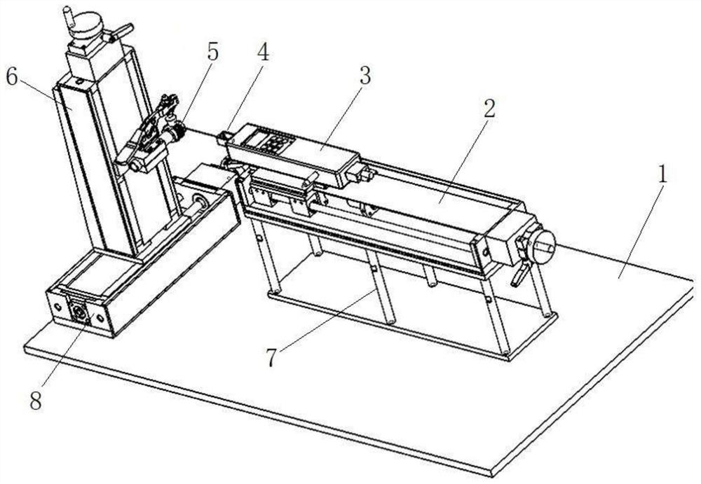
[0049] Such as Figure 1 to Figure 8 As shown, the present embodiment provides a tool for testing optical fiber connector tension and lens bonding thrust, which includes two parts: a translation platform 2 and an elevating platform 6 arranged opposite to the translation platform;

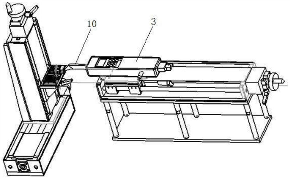
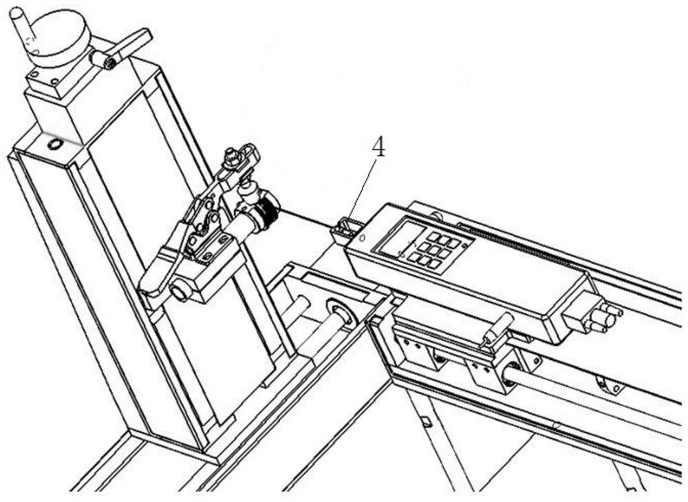
[0050] The displacement table 2 is provided with a sliding device and a push-pull gauge 3, and the sliding device drives the push-pull gauge 3 to generate a displacement, and one end of the push-pull gauge 3 is provided with a fixing fixture 4 or a thrust fixture 10;

[0051] One side of the lifting table 6 is provided with a lifting device, a winding fixture 5 and / or a loading fixture 20, and the winding fixture 5 and / or loading fixture 20 are arranged on the lifting device, and the winding fixture 5 and / or the loading fixture 20 are driven up and down by the lifting device move.

[0052]The technical solution of this embodiment is a multi-purpose machine, and different tests are realized by using...

Embodiment 2

[0059] A kind of optical fiber connector pulling force and lens bonding thrust testing tool, the structure is as described in embodiment 1, and its difference is: fixing fixture 4 comprises a rectangular body, and positioning groove 401 and narrow opening 402 (relatively) are arranged on the body For the wide opening of Example 1). Fixing jigs of this specification can be used to place (fix) cylindrical thin connectors.

Embodiment 3

[0061] A tool for testing optical fiber connector tension and lens bonding thrust, the structure is as described in Embodiment 1, the difference is that: the body of the fixing fixture 4 is also provided with a transverse opening positioning groove 403, and the transverse opening positioning groove 403 is located in the opening 402, and the transverse opening positioning groove 403 runs through the body. Through the laterally opened positioning groove 403 and the positioning groove 401, the special-shaped optical fiber connector can be effectively fixed for testing.


PUM


Abstract

The invention relates to an optical fiber connector tension and lens bonding thrust testing tool and application thereof. The optical fiber connector tension and lens bonding thrust testing tool comprises a displacement table and a lifting table opposite to the displacement table. A sliding device and a pull and push dynamometer are arranged on the displacement table, the pull and push dynamometeris driven by the sliding device to generate displacement, and a fixing clamp or a thrust clamp is arranged at one end of the pull and push dynamometer; a lifting device, a winding clamp and / or a loading clamp are / is arranged on one side of the lifting table, the winding clamp and / or the loading clamp are / is arranged on the lifting device, and the winding clamp and / or the loading clamp are / is driven by the lifting device to move up and down. The testing tool can be used for measuring the tension of the optical fiber connector and the bonding thrust of the lens, can test different types of optical fiber connectors and different specifications of adhesive optical lenses by utilizing different clamps, fills the blank of special equipment for testing the tensile force of the optical fiber connector and the bonding thrust of the lens, and is simple to operate, convenient to use and accurate in test result.

Description

technical field [0001] The invention relates to an optical fiber connector pulling force and lens bonding thrust testing tooling and an application thereof, belonging to the technical field of communication testing equipment. Background technique [0002] Optical fiber connector is a device for detachable (movable) connection between optical fiber and optical fiber. It precisely butts the two end faces of optical fiber so that the optical energy output by the transmitting optical fiber can be coupled to the receiving optical fiber to the maximum extent. And minimize the impact on the system due to its intervention in the optical link. [0003] For optical fiber connectors and optical lenses fixed by glue, they are mainly cured and bonded to the substrate by epoxy glue or UV glue, and different brands of glue have different reliability, such as the amount of glue, curing conditions, position of glue dispensing, glue Dopants and other factors will affect the final bonding str...

Claims


Application Information

Patent Timeline
Patent Type & Authority Applications(China)
IPC IPC(8): G01N3/08G01N3/04G01N19/04
CPCG01N3/08G01N3/04G01N19/04G01N2203/0017G01N2203/04Y02P40/57
Inventor 余兴社邵长国开北超徐现刚郑兆河
Owner 潍坊华光光电子有限公司
Why Eureka
Try Eureka