Unmanned aerial vehicle control method and vehicle-mounted terminal

A control method and vehicle-mounted terminal technology, applied in the field of unmanned aerial vehicles, can solve the problems of difficulty in controlling unmanned aerial vehicles, short data transmission distance, etc.

Pending Publication Date: 2020-09-04
SHANGHAI PATEO ELECTRONIC EQUIPMENT MANUFACTURING CO LTD
View PDF0 Cites 0 Cited by
  • Summary
  • Abstract
  • Description
  • Claims
  • Application Information

AI Technical Summary

Problems solved by technology

[0003] At present, the control of drones usually requires real-time manipulation by humans, so that the drones can complete the corresponding operations according to people's needs. However, when people are in no time to control (such as when driving), it is difficult to control the drone. Perform the operations that people want, and in the traditional UAV control method, in order to be able to control the UAV and receive the images transmitted by the UAV in real time, the control end usually uses WiFi technology to communicate with the UAV. The data transmission distance of the technology is short, so the remote control of the UAV cannot be realized

Method used


Image

  • Unmanned aerial vehicle control method and vehicle-mounted terminal
  • Unmanned aerial vehicle control method and vehicle-mounted terminal
  • Unmanned aerial vehicle control method and vehicle-mounted terminal

Examples


no. 1 example

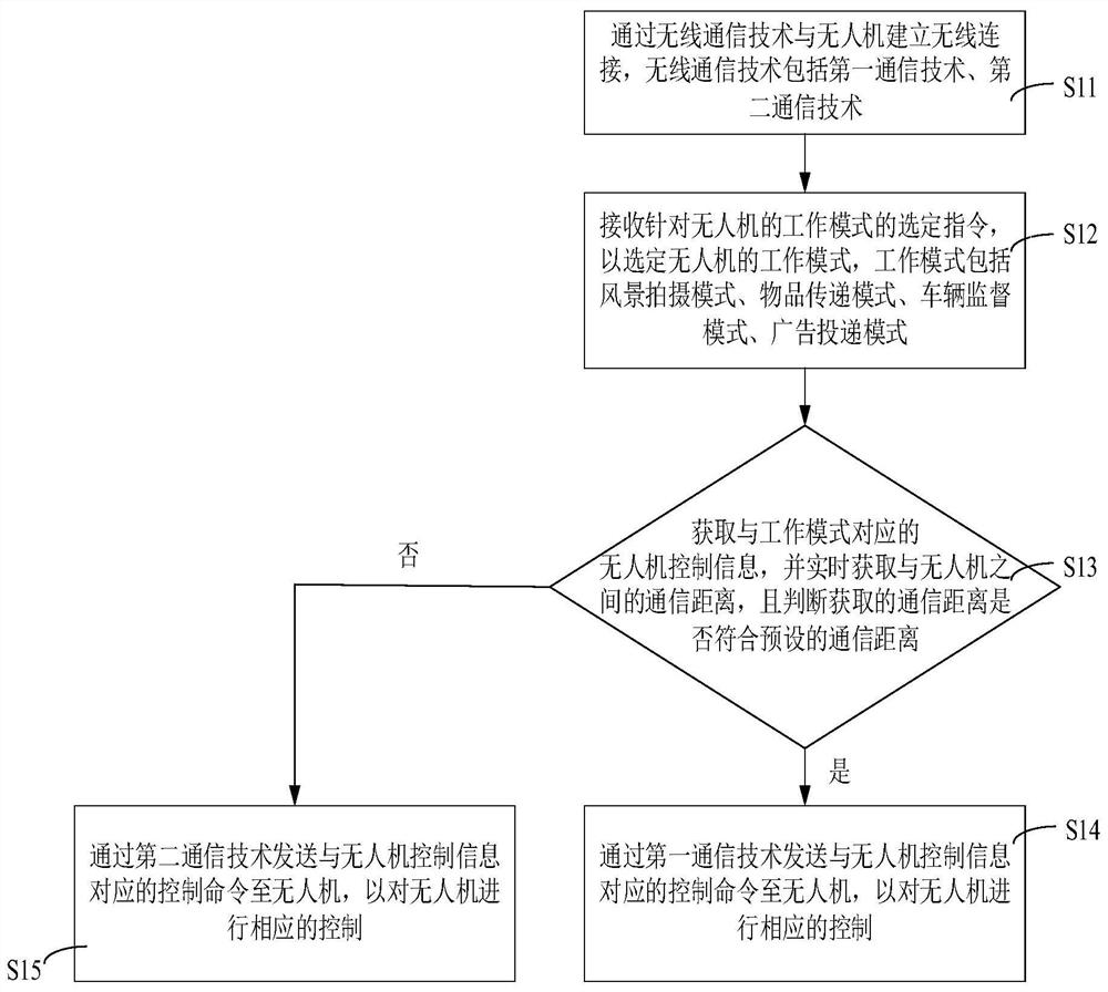
[0027] figure 1 It is a schematic flowchart of the drone control method provided by the first embodiment of the present invention. In order to clearly describe the UAV control method provided by the first embodiment of the present invention, please refer to figure 1 .

[0028] The drone control method provided by the first embodiment of the present invention includes the following steps:

[0029] S11: Establish a wireless connection with the UAV through wireless communication technology. The wireless communication technology includes the first communication technology and the second communication technology.

[0030] In one embodiment, the communication distance of the first communication technology is shorter than the communication distance of the second communication technology.

[0031] In an embodiment, the first communication technology includes but is not limited to WiFi communication technology, Bluetooth communication technology, and the like. The second communicat...

no. 2 example

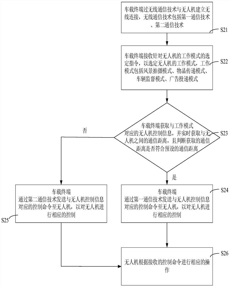
[0057] figure 2 It is a schematic flowchart of the drone control method provided by the second embodiment of the present invention. In order to clearly describe the UAV control method provided by the second embodiment of the present invention, please refer to figure 2 .

[0058] The UAV control method provided by the second embodiment of the present invention includes the following steps:

[0059] S21: The vehicle-mounted terminal establishes a wireless connection with the UAV through a wireless communication technology, and the wireless communication technology includes a first communication technology and a second communication technology.

[0060] S22: The vehicle-mounted terminal receives a selection instruction for the working mode of the drone to select the working mode of the drone. The working modes include landscape shooting mode, item delivery mode, vehicle supervision mode, and advertisement delivery mode.

[0061] S23: The vehicle-mounted terminal obtains the ...

no. 3 example

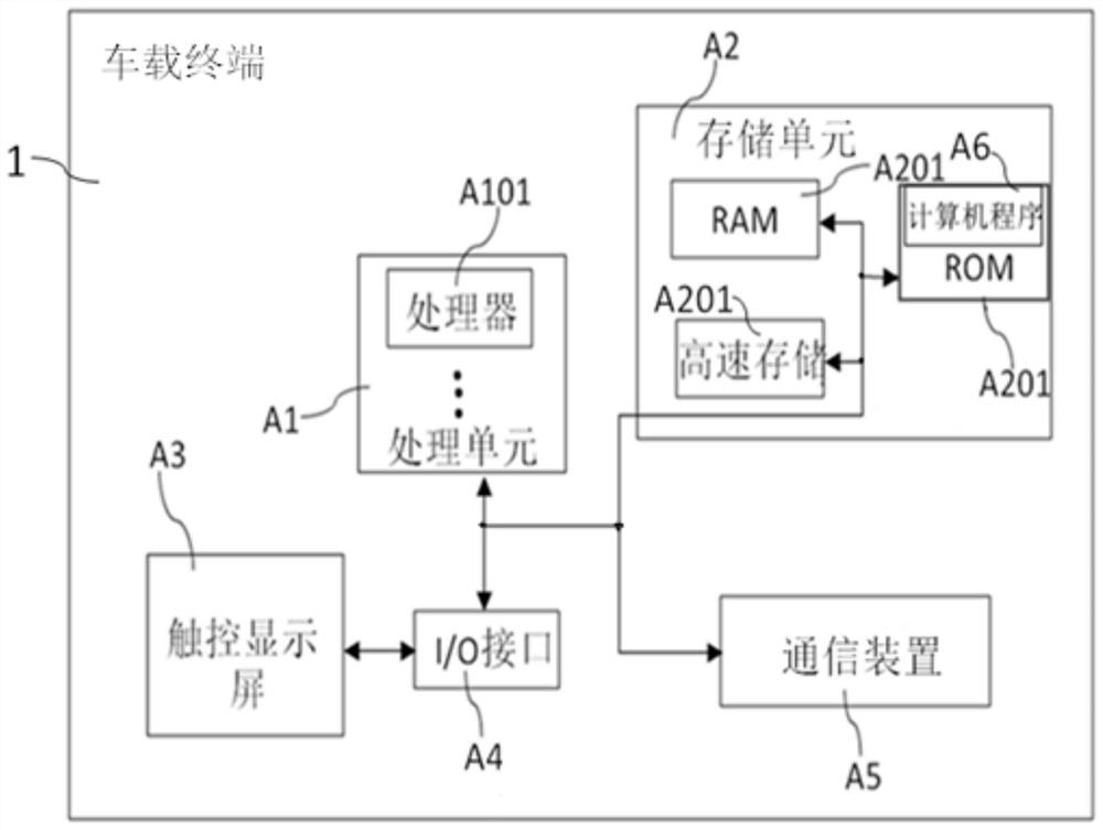
[0069] image 3 It is a schematic structural diagram of the vehicle-mounted terminal provided by the third embodiment of the present invention. Figure 4 It is a schematic diagram of the connection structure between the vehicle-mounted terminal and the drone provided by the third embodiment of the present invention. In order to clearly describe the vehicle-mounted terminal provided by the third embodiment of the present invention, please refer to image 3 with Figure 4 .

[0070] The vehicle-mounted terminal 1 provided by the third embodiment of the present invention includes: a processor A101 and a memory A201, wherein the processor A101 is used to execute the computer program A6 stored in the memory A201 to realize the drone as described in the first embodiment The steps of the control method.

[0071] In an implementation manner, the vehicle-mounted terminal 1 provided in this embodiment may include at least one processor A101 and at least one memory A201. Wherein, at...


PUM


Abstract

The invention belongs to the technical field of unmanned aerial vehicles, and relates to an unmanned aerial vehicle control method and a vehicle-mounted terminal. The unmanned aerial vehicle control method comprises: establishing wireless connection with an unmanned aerial vehicle through a wireless communication technology, wherein the wireless communication technology comprises a first communication technology and a second communication technology; receiving a selection instruction for the working modes of the unmanned aerial vehicle to select the working modes of the unmanned aerial vehicle, wherein the working modes include a landscape shooting mode, an article delivery mode, a vehicle supervision mode and an advertisement delivery mode; obtaining unmanned aerial vehicle control information corresponding to the working modes, and obtaining the communication distance between the unmanned aerial vehicle and the unmanned aerial vehicle in real time; and if the acquired communication distance conforms to the preset communication distance, sending a control command corresponding to the unmanned aerial vehicle control information to the unmanned aerial vehicle through the first communication technology so as to correspondingly control the unmanned aerial vehicle; and if the acquired communication distance does not accord with the preset communication distance, sending a control command corresponding to the unmanned aerial vehicle control information to the unmanned aerial vehicle through the second communication technology so as to correspondingly control the unmanned aerialvehicle.

Description

technical field [0001] The invention relates to the technical field of unmanned aerial vehicles, in particular to an unmanned aerial vehicle control method and a vehicle-mounted terminal. Background technique [0002] In recent years, the technology of small civilian drones has developed rapidly, and its application fields have become more and more extensive, such as power inspection, film and television drama shooting, landscape shooting, outdoor program shooting and other applications. With the development of technology and the reduction of cost, drones have gradually entered the lives of ordinary people. In riversides, parks and other places, people often see people holding remote control handles to remotely control drones in the air for aerial photography. The UAV here refers to a small and light aircraft, equipped with a high-definition camera, and performs aerial flight shooting under the condition of wireless remote control through a remote control handle. The remote...

Claims


Application Information

Patent Timeline
IPC IPC(8): G05D1/10
CPCG05D1/101
Inventor 张仁建
Owner SHANGHAI PATEO ELECTRONIC EQUIPMENT MANUFACTURING CO LTD
Why Eureka
Try Eureka