Automatic drilling and milling system and method and drilling and milling production line

An automatic drilling, drilling and milling technology, applied in the direction of automatic control devices, manufacturing tools, other manufacturing equipment/tools, etc., can solve problems such as inability to complete waist hole milling, inability to adapt to workpiece wall thickness differences, and processing errors

Pending Publication Date: 2017-07-07
SHANGHAI FANUC ROBOTICS
View PDF19 Cites 16 Cited by
  • Summary
  • Abstract
  • Description
  • Claims
  • Application Information

AI Technical Summary

Problems solved by technology

[0007] 1) The robot can only perform the function of transportation, that is, because the robot only completes the positioning operation of the hole to be processed, this system can only reflect the transportation function of the robot, but cannot demonstrate and make full use of the advantages of the robot such as flexibility;
[0008] 2) The dedicated drilling execution terminal weakens the rigidity of the entire automatic milling system, that is, the drilling process is completed by a dedicated drilling execution terminal, forcing the drilling execution terminal to integrate a servo system (providing drilling axial feed) and preloading The tightening device (providing the pressing force, mainly used to weaken the vibration during processing and improve the processing accuracy) and other components, thus greatly increasing the size and quality of the tooling part of the robot head, which will further weaken the entire automatic drilling system. stiffness;
[0009] 3) It is impossible to complete operations such as waist hole milling, which makes the function limited; because the special drilling execution terminal is only equipped with the drilling axial feed servo, it is impossible to process the waist hole that requires the other two directions of feed movement. This restricts the development and application of new functions;
[0010] 4) The pre-compression device cannot adapt to the change of the workpiece wall thickness, resulting in new machining errors; this is mainly because the robot needs to move to a predetermined position with a predetermined attitude before drilling in accordance with the sequence of the general processing process, and it is integrated in a special The pre-compression device of the drilling execution terminal automatically contacts the workpiece and applies a compression force (preset) before drilling can start; and the deformation of the workpiece due to the compression force will reduce the machining accuracy, and Since the pressing force is the preset pressing force, it cannot adapt to the difference in wall thickness of each drilling position of the workpiece, which will eventually cause local holes, which will further reduce the processing accuracy;
[0011] 5) Offline compensation; that is, because the current robot automatic drilling system uses external measuring equipment for robot drilling error compensation to ensure that the machining accuracy meets the requirements, but this compensation method is a one-time compensation, which has great disadvantages. Determinism, for example: because the measurement is only for a specific sample, it cannot eliminate the size difference between the workpieces, nor can it eliminate the positioning error of different workpieces positioned on the tooling; and the system error caused by long-term production cannot be eliminated, only when there is an error Only qualified parts can be used to correct errors, which in turn will cause increased production costs such as time delays and work delays;
[0012] 6) The error caused by insufficient robot stiffness cannot be eliminated; this is because the error compensation amount caused by insufficient robot stiffness is not a fixed value or changes linearly, and the offline compensation method will instead cause over-compensation of some holes and cause processing errors. The current system cannot completely eliminate the errors caused by insufficient rigidity of the robot;
[0013] 7) The economy and flexibility are poor; this is because the special drilling execution terminal is a special customized equipment, its own customization cost, and the cost of the robot's load increase caused by its large mass make it economical In addition, for the holes with a large proportion and relatively low precision requirements, the special drilling execution terminal is redundant; in addition, the automatic drilling system is limited by the special drilling execution terminal, and it needs to be used for different hole groups of the same workpiece. Different processes are used, and even the execution terminal needs to be replaced to complete, which reduces the processing efficiency and flexibility; at the same time, the automatic drilling system is not compatible with processing such as waist holes, which limits the range of motion of the robot and reduces its flexibility.

Method used


Image

  • Automatic drilling and milling system and method and drilling and milling production line
  • Automatic drilling and milling system and method and drilling and milling production line
  • Automatic drilling and milling system and method and drilling and milling production line

Examples


Embodiment 1

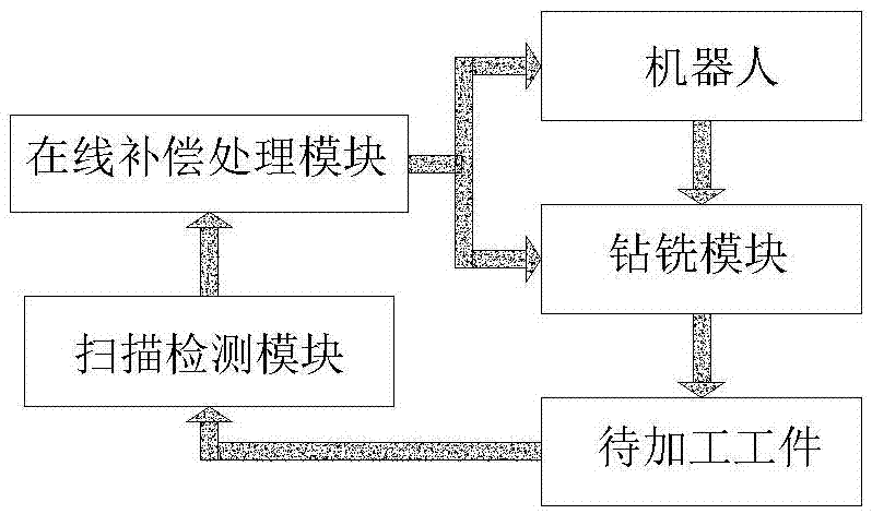
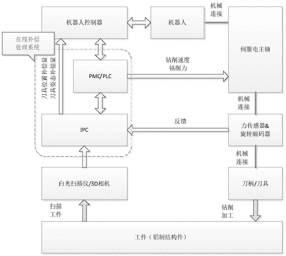
[0109] figure 1 It is a schematic diagram of the module structure of the automatic drilling and milling system in the embodiment of the application; as figure 1 As shown, an automatic drilling and milling system in this embodiment can be applied to operations such as drilling / milling on workpieces to be processed (such as aluminum structural parts, etc.) fixed on a processing table, and the system may include:

[0110] A robot (i.e. an industrial robot) can be fixedly arranged at a position close to the above-mentioned processing table, so that the robot can be used to perform operations such as drilling / milling on the workpiece to be processed;

[0111] The drilling and milling module is connected with the above-mentioned robot (that is, mechanically connected and fixed on the above-mentioned robot), which can make the robot drive the drilling and milling module to perform operations such as drilling / milling on the workpiece to be processed;

[0112] The scanning detection m...

Embodiment 2

[0124] The application also provides a drilling and milling production line, comprising:

[0125] Material loading sub-production line, at least one drilling and milling sub-production line and deburring processing sub-production line, and the automatic drilling and milling system in the first embodiment of the drilling and milling sub-production line;

[0126] Specifically, after the feeding sub-generation line fixes the workpiece to be processed on the processing table, the drilling and milling sub-generation line performs drilling / milling operations on the workpiece to be processed fixed on the processing table, and the deburring processing sub-generation line removes the workpiece after drilling and milling. After the sub-system performs the drilling / milling operation, the workpiece to be processed is deburred.

Embodiment 3

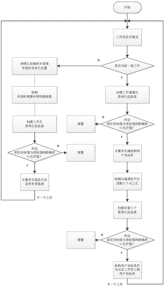
[0128] image 3 It is a schematic flow chart of robot position / posture online compensation in the automatic drilling and milling method in the embodiment of the present application; Figure 4 It is a schematic flow chart of real-time adjustment of cutting parameters in the automatic drilling and milling method in the embodiment of the present application; Figure 1~4 As shown, the present application also provides an automatic drilling and milling method, which can be based on the above-mentioned embodiment 1 and / or embodiment 2, including:

[0129] Fix the workpiece to be processed on the processing table;

[0130] Use the robot to drive the drilling and milling module to perform drilling / milling operations on the workpiece to be processed;

[0131] The scanning detection module obtains the processing position information and actual cutting parameter information of the drilling / milling operation;

[0132] The online compensation processing module corrects the drilling / mill...


PUM


Abstract

The invention discloses an automatic drilling and milling system and method and a drilling and milling production line, and relates to the technical field of electromechanical machining. The automatic drilling and milling system and method and the drilling and milling production line can be applied to the process of machining to-be-machined aluminum workpieces and the like through a milling machining center and/or an automatic robot drilling and milling system and the like; and in other words, 3D scanning and other surveillance technologies are utilized for conducting online surveillance and compensation on the robot track, and accordingly accurate machining of the to-be-machined workpieces is achieved.

Description

technical field [0001] The invention relates to the technical field of electromechanical processing, in particular to an automatic drilling and milling system and method, and a drilling and milling production line. Background technique [0002] With the rapid development of social automation and informatization, the manufacturing industry's requirements for machinery manufacturing and assembly technology tend to be more and more high-quality, high-efficiency, and low-cost, and flexibility and informatization are one of the important symbols to meet the above requirements One, especially in industries such as aircraft and automobiles, because the processing of holes in aluminum structural parts has evolved from traditional manual drilling and milling to special automatic drilling and milling systems and milling centers, and even robots have been realized. Automatic drilling and milling system to complete drilling and milling processing such as aluminum structural parts. [0...

Claims


Application Information

Patent Timeline
Patent Type & Authority Applications(China)
IPC IPC(8): B23P23/02B23Q15/12B23Q17/24B23Q17/09B23Q17/10B23Q17/20B23Q7/00
CPCB23P23/02B23Q7/00B23Q15/12B23Q17/09B23Q17/10B23Q17/20B23Q17/2409
Inventor 吴钰屾黄万永陆晨齐党进钱晖童梁
Owner SHANGHAI FANUC ROBOTICS
Why Eureka
Try Eureka