A kind of led drive circuit, lamp board and display panel

A LED drive and circuit technology, applied in static indicators, instruments, etc., can solve the problems of low consistency of individual LED brightness and inconsistent pwm signal response, so as to improve the transfer yield, occupy a small space, and reduce production costs Effect

Active Publication Date: 2021-02-23
深圳市TCL高新技术开发有限公司
View PDF9 Cites 0 Cited by
  • Summary
  • Abstract
  • Description
  • Claims
  • Application Information

AI Technical Summary

Problems solved by technology

[0004] The purpose of this application is to provide an LED drive circuit, a lamp board and a display panel, aiming at solving the inconsistencies in the responses of different LEDs to the PWM signal with the same duty cycle when the traditional pwm drive technology is used to drive the LED , leading to the problem of low brightness consistency between individual LEDs

Method used


Image

  • A kind of led drive circuit, lamp board and display panel
  • A kind of led drive circuit, lamp board and display panel
  • A kind of led drive circuit, lamp board and display panel

Examples


Embodiment Construction

[0030] In order to make the technical problems, technical solutions and beneficial effects to be solved by the present application clearer, the present application will be further described in detail below in conjunction with the accompanying drawings and embodiments. It should be understood that the specific embodiments described here are only used to explain the present application, and are not intended to limit the present application.

[0031] It should be understood that the terms "first", "second" and the like appearing in many places throughout the text are only for descriptive purposes, and should not be understood as indicating or implying relative importance or implicitly specifying the quantity of indicated technical features. Thus, a feature defined as "first" and "second" may explicitly or implicitly include one or more of these features. In the description of the present application, "plurality" means two or more, unless otherwise specifically defined.

[0032] ...


PUM


Abstract

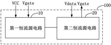
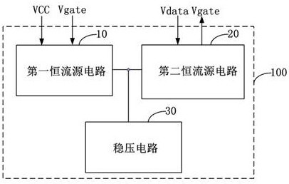
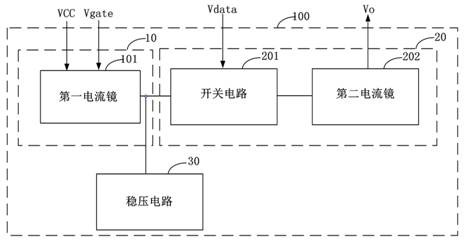
An LED driving circuit, a lamp board and a display panel, wherein the LED driving circuit includes a first constant current source circuit and a second constant current source circuit, the first constant current source circuit is used to work when receiving a power signal, and will receive The received column data signal is output; the second constant current source circuit is used to work when receiving the row scanning signal, and transmit the column data signal to the LED to instruct the LED to emit light. The above-mentioned LED drive circuit realizes the constant current control of the LED through the cooperation of the first constant current source circuit and the second constant current source circuit. The output current of the LED drive circuit is not affected by the LED load, so that the individual LEDs The brightness consistency between the two is high, which makes the gray scale display more uniform.

Description

technical field [0001] The present application belongs to the field of display technology, and in particular relates to an LED driving circuit, a lamp board and a display panel. Background technique [0002] Micro LED, also known as micro LED, is a new generation of display technology. Compared with traditional LED display technology, it has the advantages of higher brightness, better luminous efficiency and lower power consumption. At present, the PWM (pulse width modulation, pulse width modulation) driving technology is usually used to drive the micro-LED, and the brightness of the micro-LED is controlled by changing the duty cycle of the high level in the pwm signal. However, the pwm control technology belongs to constant voltage control. When receiving a pwm signal with the same duty cycle, different micro-LEDs have different currents, resulting in low brightness consistency among individual micro-LEDs. For other types of LEDs, the same problem as above is faced. [00...

Claims


Application Information

Patent Timeline
Patent Type & Authority Patents(China)
IPC IPC(8): G09G3/32
CPCG09G3/32
Inventor 闫晓林蔡胜强林智远谢相伟
Owner 深圳市TCL高新技术开发有限公司
Why Eureka
Try Eureka