Optical radiator

An optical radiation and radiator technology, applied in the field of optical radiators, can solve the problem that the optical radiator cannot meet the application requirements of wide radiation angle and high radiation intensity at the same time.

Pending Publication Date: 2020-09-04
哈尔滨海格微电子科技有限公司 +1
View PDF0 Cites 0 Cited by
  • Summary
  • Abstract
  • Description
  • Claims
  • Application Information

AI Technical Summary

Problems solved by technology

However, under a specific driving power, the radiant luminous flux of a single light-emitting chip is a fixed value, that is, the radiation intensity of the light radiator is a fixed value. In this case, the radiation angle needs to be narrow to obtain high radiation intensity. On the contrary, if you want to obtain a wide radiation angle, the radiation intensity will be lower, so that the existing optical radiator cannot meet the application requirements of wide radiation angle and high radiation intensity at the same time.

Method used


Image

  • Optical radiator
  • Optical radiator
  • Optical radiator

Examples


Embodiment Construction

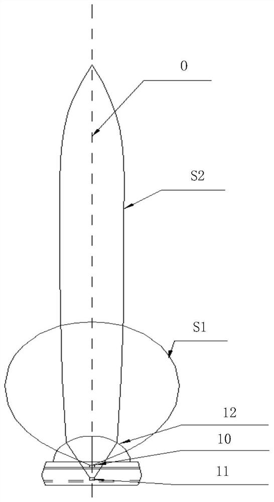
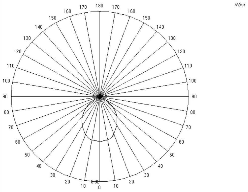
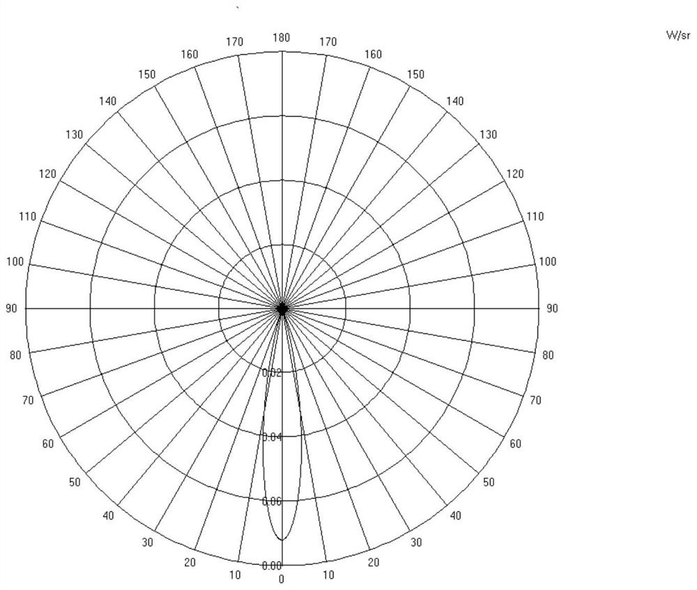
[0034] As in the background art, existing optical radiators cannot meet the application requirements of wide radiation angle and high radiation intensity at the same time. The inventors found that the main reason for this problem is that the light radiator composed of a single light-emitting chip 10, 11 and the convex lens 12, the center position of the light-emitting chip 10 or 11 is usually on the main optical axis O of the convex lens 12 , its peak radiation intensity is also on the main optical axis O of the convex lens 12, the spatial distribution of the radiation is conical S1, S2 and its axis coincides with the main optical axis O of the convex lens 12, as figure 1 Shown is an optical simulation relationship diagram of the radiation intensity and radiation angle of light emitted by a single light-emitting chip 10, 11 and a convex lens 12, figure 2 It is the actual test chart of the radiation intensity and radiation angle of the light emitted by a single light-emitting ...


PUM


Abstract

The invention provides an optical radiator. The optical radiator comprises a substrate; a plurality of light-emitting chips arranged on the substrate; a convex lens which is arranged on the substrateand the tops of the plurality of light-emitting chips, wherein the convex lens covers the plurality of light-emitting chips, so that light rays emitted by any light-emitting chips penetrate through the convex lens and then are emitted out; the shape of the convex lens is preset, and the relative position of any light-emitting chip and the main optical axis of the convex lens is preset; a controller which is respectively connected with the plurality of light-emitting chips, wherein the controller drives the light-emitting chips to emit light according to preset driving power, and controls the plurality of light-emitting chips to emit light at the same time or emit light in sequence according to a preset control manner, so that the radiation angles of the plurality of light-emitting chips are preset radiation angles, the radiation intensity is preset radiation intensity, and the optical radiator can meet the application requirements for wide radiation angles and high radiation intensity.

Description

technical field [0001] The present invention relates to the technical field of light emitting devices, more specifically, to a light radiator. Background technique [0002] Optical radiators or optical emitters are formed by packaging a single light-emitting chip with a single convex lens, and are mainly used in the fields of data transmission, scanning, and detection of visible and invisible light. [0003] Generally, the stronger the radiation intensity of the optical radiator, the better, and the wider the radiation angle, the better. However, under a specific driving power, the radiant luminous flux of a single light-emitting chip is a fixed value, that is, the radiation intensity of the light radiator is a fixed value. In this case, the radiation angle needs to be narrow to obtain high radiation intensity. On the contrary, if you want to obtain a wide radiation angle, the radiation intensity will be lower, so that the existing optical radiator cannot meet the applicati...

Claims


Application Information

Patent Timeline
Patent Type & Authority Applications(China)
IPC IPC(8): H01L33/58H01L33/48H01L25/075
CPCH01L25/0753H01L33/48H01L33/58
Inventor 杨家象张晓明
Owner 哈尔滨海格微电子科技有限公司
Why Eureka
Try Eureka