A Miniaturized Antenna Based on Wrinkled Microstrip Line

A technology of microstrip lines and folds, which is applied in the field of microwave applications, can solve problems such as the inability to simultaneously achieve low profile, high gain and wide scanning angle, poor antenna radiation performance, and reduce the effective radiation area of ​​the antenna, achieving compact structure and high Effects with high gain and practicality

Active Publication Date: 2021-02-26
湖南赛博诺格电子科技有限公司
View PDF6 Cites 0 Cited by
  • Summary
  • Abstract
  • Description
  • Claims
  • Application Information

AI Technical Summary

Problems solved by technology

However, there are some defects in these technologies. Even if the miniaturization of the microstrip antenna is realized, the effective radiation area of ​​the antenna is reduced, which will lead to the deterioration of the radiation performance of the antenna, and it is impossible to achieve low profile, high gain and wide scanning angle at the same time. performance

Method used


Image

  • A Miniaturized Antenna Based on Wrinkled Microstrip Line
  • A Miniaturized Antenna Based on Wrinkled Microstrip Line
  • A Miniaturized Antenna Based on Wrinkled Microstrip Line

Examples


Embodiment Construction

[0022] The following will clearly and completely describe the technical solutions in the embodiments of the present invention. Obviously, the described embodiments are only some of the embodiments of the present invention, rather than all the embodiments. Based on the embodiments of the present invention, all other embodiments obtained by persons of ordinary skill in the art without creative work fall within the protection scope of the present invention:

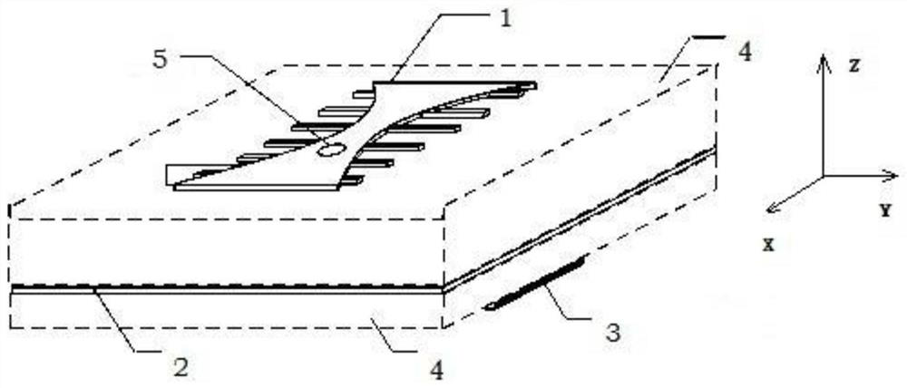
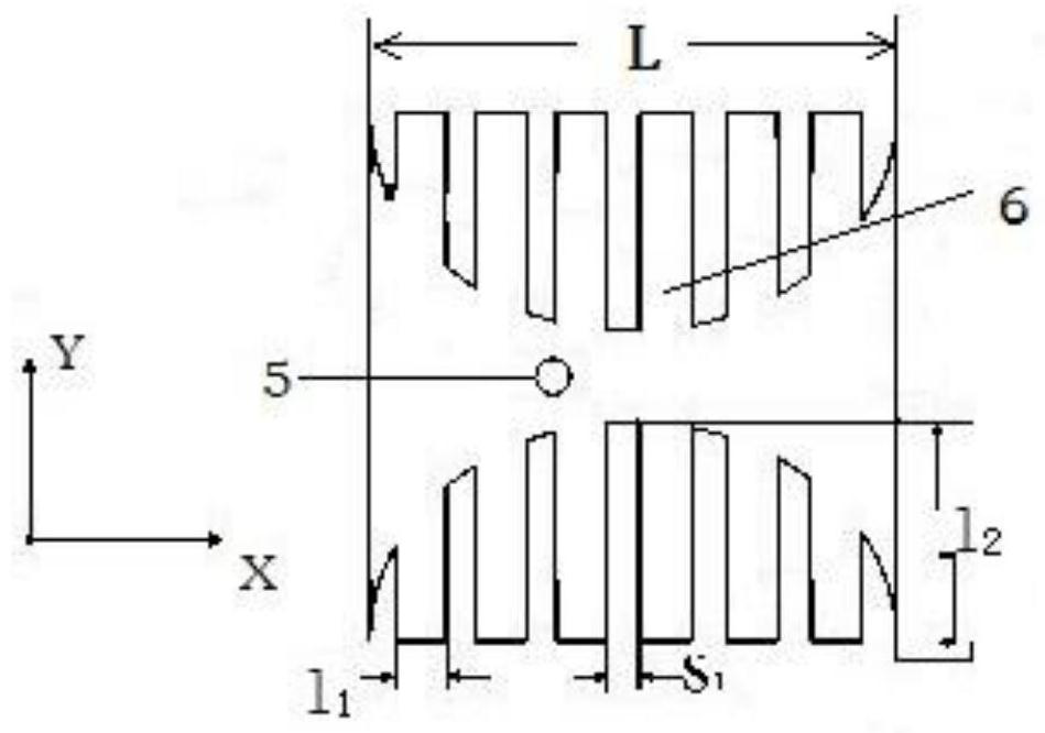
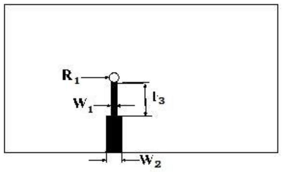
[0023] A miniaturized antenna based on corrugated microstrip lines, such as Figure 1 to Figure 3 As shown, it includes the top layer 1, the middle floor layer 2 and the bottom power supply layer 3 arranged sequentially from top to bottom, and a dielectric layer 4 is bonded between the top layer and the middle floor layer, and between the middle floor layer and the bottom power supply layer , the top layer, the middle floor layer, the bottom feeder layer and the dielectric layer all have through holes, all the through holes ...


PUM

PropertyMeasurementUnit
lengthaaaaaaaaaa
radiusaaaaaaaaaa
thicknessaaaaaaaaaa

Abstract

The invention discloses a miniaturized antenna based on a folded micro-strip line. The miniaturized antenna comprises a top layer, a middle floor layer and a bottom feeding layer arranged in turn fromtop to bottom. A dielectric layer is bonded between the top layer and the middle floor layer, and a dielectric layer is bonded between the middle floor layer and the bottom feeding layer. The top layer is a metal patch, and the patch body edge where the non-radiation side of the metal patch is located is etched to form multiple strip-shaped metal bands which constitute a folded band group. The free ends of the multiple strip-shaped metal bands are flush with the non-radiation side of the metal patch. The miniaturized antenna based on a folded micro-strip line achieves better radiation characteristic and more comprehensive performance, but also has the characteristics of high gain, wide radiation angle and low profile. Moreover, the miniaturized antenna is compact and easy to manufacture,can help to improve the performance of the communication system, and is of high practicability.

Description

technical field [0001] The invention relates to the field of microwave application technology, in particular to a miniaturized antenna based on a corrugated microstrip line. Background technique [0002] Microstrip antenna is a new type of antenna that has been gradually developed in the past thirty years. In recent years, in many microwave and antenna systems, due to its small size, light weight and low cost, miniaturized microstrip antennas are used in engineering applications. It is of great significance in the field, such as for the design of handheld wireless communication equipment and high-performance antenna arrays, etc., and has achieved a lot of results in the design method. [0003] Common microstrip antenna miniaturization techniques include loading short-circuit probes, slotting, using high dielectric constant dielectric plates, and using composite left and right hand structures. However, there are some defects in these technologies. Even if the miniaturization...

Claims


Application Information

Patent Timeline
Patent Type & Authority Patents(China)
IPC IPC(8): H01Q1/38H01Q1/48H01Q1/50
Inventor 柴进陆佳元胥文泉唐石画魏蕾
Owner 湖南赛博诺格电子科技有限公司
Why Eureka
Try Eureka