
Projection device, rear-view device and motor vehicle

A technology for projection devices and motor vehicles, which is applied to projection devices, printing devices, signal devices, etc., can solve problems such as reflection loss and imaging error, and achieve the effects of low image error, avoidance of color deviation, and good color stability.

Inactive Publication Date: 2020-05-05
SMR PATENTS S A R L
View PDF34 Cites 0 Cited by
  • Summary
  • Abstract
  • Description
  • Claims
  • Application Information

AI Technical Summary

Problems solved by technology

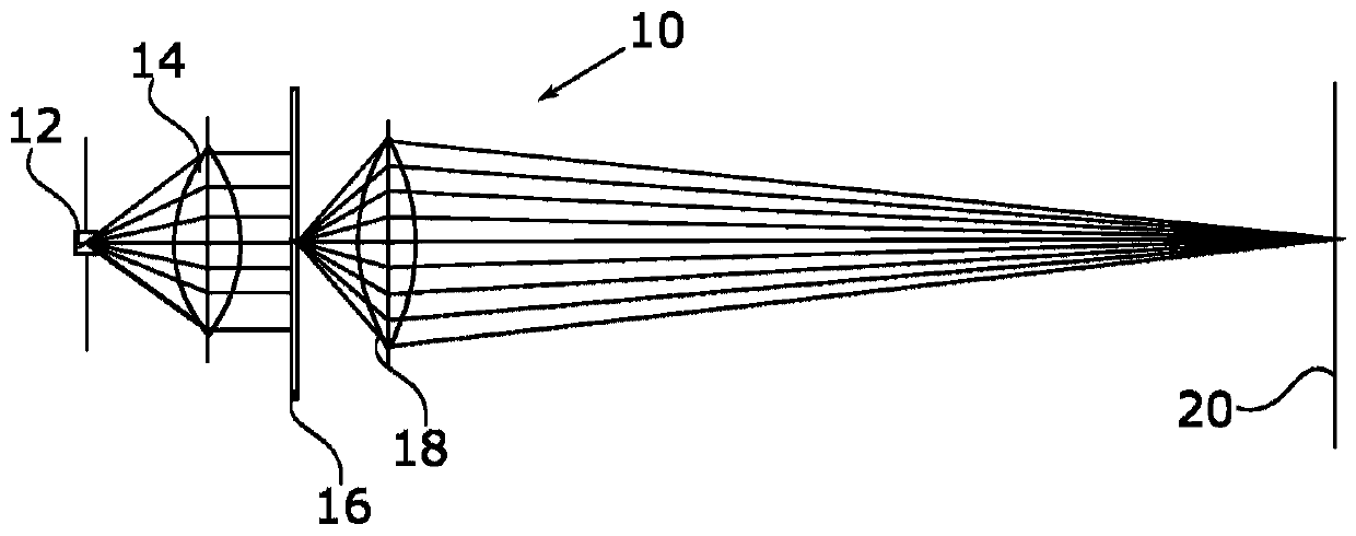
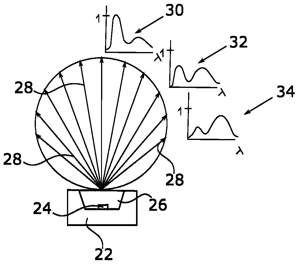
This imaging error also occurs due to the influence of the color distortion of the lenses 14, 18
Furthermore, reflection losses occur each time the light beam penetrates the interface between the lenses 14, 18 or the mask 16 and the air due to so-called Fresnel reflections.

Method used


Image

  • Projection device, rear-view device and motor vehicle
  • Projection device, rear-view device and motor vehicle
  • Projection device, rear-view device and motor vehicle

Examples


Embodiment Construction

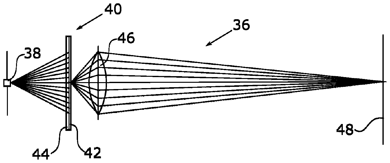
[0034] exist image 3 The projection device according to the invention, which is designated generally at 36 , comprises a light source 38 in the form of a blue laser diode, which illuminates a light mask 40 . It goes without saying that a plurality of laser diodes can also be used.

[0035] The light mask 40 includes a light mask layer 42, and the light mask layer has a plurality of image 3 Openings, not shown, define the optical information to be projected. The light mask 40 also includes a coating 44 comprising at least one luminescent material. In the example shown, the coating is arranged on the side of the mask 40 facing the light source 38; however, the coating 44 can also be mounted on the other side of the mask 40 or also on both sides. installation, especially if the mask 40 is partially optically transparent.

[0036] The one or more emissive materials of coating 44 are excited to fluoresce and / or phosphoresce by light emitted by light source 38 . It can be achie...


PUM


Abstract

The invention relates to a projection device (36) for projecting visual information, in particular in the form of a logo or warning signal, and to a projection surface (48), having a light source (38)which has an emission maximum at a first wavelength, a mask (40) which is arranged in the beam path of the light source (38) and has at least one opening which makes available the visual information,and at least one optical lens (46, 50) arranged in the beam path, wherein the mask (40) and / or the lens (46, 50) have / has a coating (44) with at least one fluorescent material, the excitation wave length of which corresponds to the first wavelength, and which emits light at least one second wavelength. The invention also relates to a rear-view device and to a motor vehicle having such a projection device (36).

Description

technical field [0001] The invention relates to a projection device for projecting icons as well as to a rear view system and a motor vehicle having such a projection device. Background technique [0002] Rear vision devices for motor vehicles provide at least a legally compliant image of the area behind the motor vehicle and belong to the subset of devices for indirect vision. The rear vision device provides images and views of objects that are not in the driver's direct field of view (ie in a direction opposite, left, right, below and / or above the driver's line of sight). the driver's line of sight, especially in the direction of the line of sight, is not entirely satisfactory, for example, may be obstructed by vehicle components of the host vehicle, for example by body parts, in particular A-pillars, the roof structure and / or the bonnet, In addition, other vehicles and / or objects outside the vehicle may cause visual obstructions which may impede the vision in such a way ...

Claims


Application Information

Patent Timeline
Patent Type & Authority Applications(China)
IPC IPC(8): F21S43/16B60Q1/26
CPCB60Q1/26B60Q2400/50F21S43/16G02B27/09G03B21/204G03B29/00G03B21/001F21W2103/60F21S43/26B60Q9/00B60R1/06B60R11/04B60R2011/004
Inventor E·迈尔
Owner SMR PATENTS S A R L
Learn More