
Medical instrument for patella fracture repair surgery

A medical device, the technology of patella fracture, applied in the field of medical devices, can solve the problems of secondary injury of patella, waste of medical resources, inability to reverse rotation, etc., and achieve the effect of quick relief

Inactive Publication Date: 2020-09-08
郜鹏
View PDF1 Cites 2 Cited by
  • Summary
  • Abstract
  • Description
  • Claims
  • Application Information

AI Technical Summary

Problems solved by technology

[0006] 1) One of the above-mentioned equipment cannot solve the operation involving the extraction of two single wire ends. In this case, only two medical staff can be used to operate two of the above-mentioned equipment to participate in the operation, which not only wastes medical resources, but also occupies the working space of the chief surgeon, reducing surgical efficiency;
[0007] 2) Patella repair surgery will determine a wire binding method according to the actual fracture situation, and the number of wire ends is also determined. In the technical solution involved in the above-mentioned invention patent, the single wire end tensioning mechanism and the double wire end The tensioning mechanisms are respectively located at both ends of the rotating mechanism, that is, the above-mentioned equipment has both a single-thread tensioning mechanism and a double-thread tensioning mechanism, and only one tensioning mechanism is used in the operation, and the other tensioning mechanism It must be idle. Since the above-mentioned equipment is operated by hand, the idle tensioning mechanism not only occupies the operation space, but also increases the load on the arms of the medical staff when operating, increasing the burden on the medical staff;
[0008] 3) With reference to paragraph [0065], paragraph [0066], paragraph [0067] of the description of the above-mentioned patent document and the drawings in the description Figure 23 , Fig. 24 and Fig. 25, it can be seen that since it adopts the first sleeve (311) with the active helical teeth (312) and the second sleeve (313) with the driven helical teeth (314) for transmission, the desired The technical effect is one-way transmission and cannot be rotated in the opposite direction; because in the process of tightening the wire thread, the surgeon needs to try the tightening force several times before tying the wire head, so that the bone suture can be restored to the best effect, so , in the process of tightening the steel wire, if excessive tightening needs to be loosened, the equipment involved in the above-mentioned patent cannot realize the technical effect of loosening the steel wire, and only the hand-tightened bolt one (214) or hand-tightened Bolt two (227) unclamps the steel wire end that is compressed, and after recovering the initial state of above-mentioned equipment, compresses the steel wire end to tighten up again, and like this not only has a strong impact on operation efficiency, also can cause secondary injury to the damaged patella;
[0009] 4) Since the driving helical teeth (312) and the driven helical teeth (314) are actually ratchet transmission structures, and the number of teeth is fixed, the minimum number of steps that can be realized by one round of circumferential rotation is also fixed, which cannot be achieved Stepless transmission, therefore, one less step is too loose and one more step is too tight during the operation. Even if the number of helical teeth is increased, the degree of looseness or tightness can only be reduced, and cannot be completely eliminated. Moreover, the number of teeth increases , the tooth shape will become smaller, and the material has a stress limit, so the number of helical teeth cannot be infinitely increased;
[0010] 5) With reference to the technical features described in paragraph [0065], paragraph [0066] and paragraph [0067] of the above-mentioned patent document description, it can be seen that there is no self-locking transmission between the transition gear one (315) and the drive shaft 238 structure, therefore, the technical effect in paragraph [0065] "When the driving helical tooth 312 rotates in reverse, the driving helical tooth 312 will press the driven helical tooth 314 and make the sleeve two 313 float away from the sleeve one 311 "It cannot be realized, because after the steel wire is tightened for the first time, there is a certain tension in the steel wire, which will cause the driven helical tooth 314 to have a tendency to rotate in the opposite direction. Furthermore, the floating spring 317 pushes the sleeve two 313 to the top Tight to the second sleeve 313, therefore, the actual situation is that when the active helical gear 312 rotates in reverse, the second sleeve 313 will not float away from the first sleeve 311, but reversely rotates together with the active helical gear 312, so that the retraction The tight steel wire is loosened, and the technical effect of repeatedly pulling the wrench 305 to tighten the steel wire cannot be achieved. Such technical defects make the technical solution involved in the above patent unable to achieve its technical purpose, let alone solve the problems existing in the prior art. insufficient

Method used


Image

  • Medical instrument for patella fracture repair surgery
  • Medical instrument for patella fracture repair surgery
  • Medical instrument for patella fracture repair surgery

Examples


Embodiment Construction

[0063] The present invention will be further described below in conjunction with specific embodiments. The exemplary embodiments and descriptions of the present invention are used to explain the present invention, but not as a limitation to the present invention.

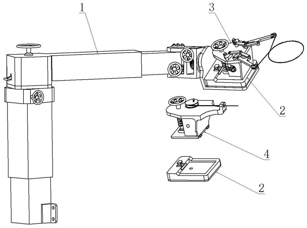
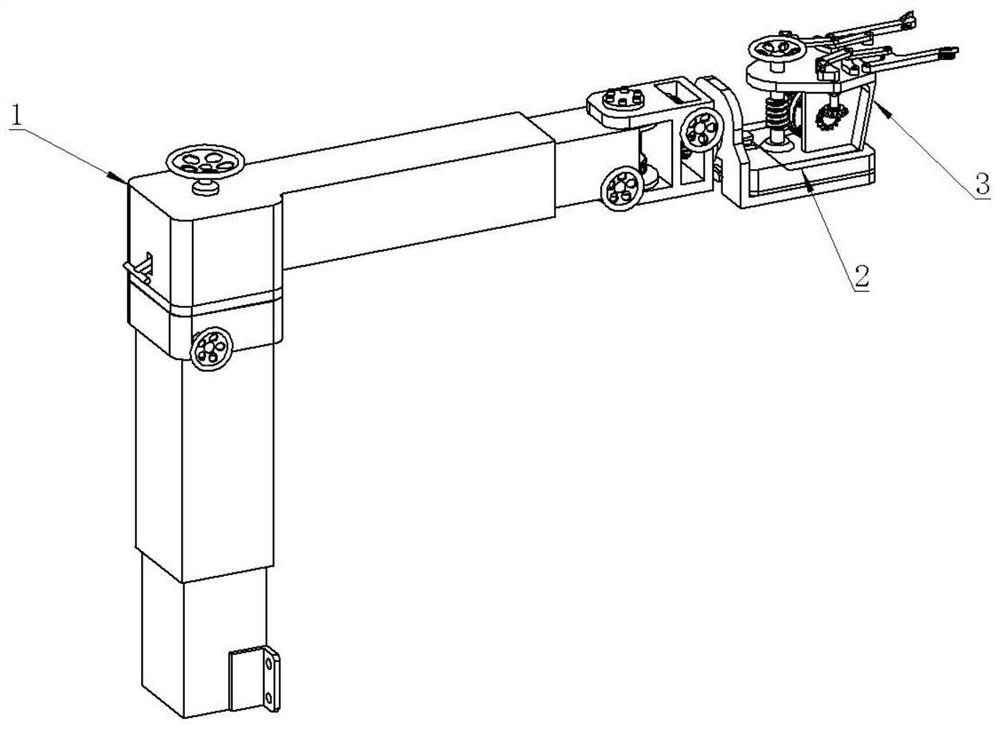
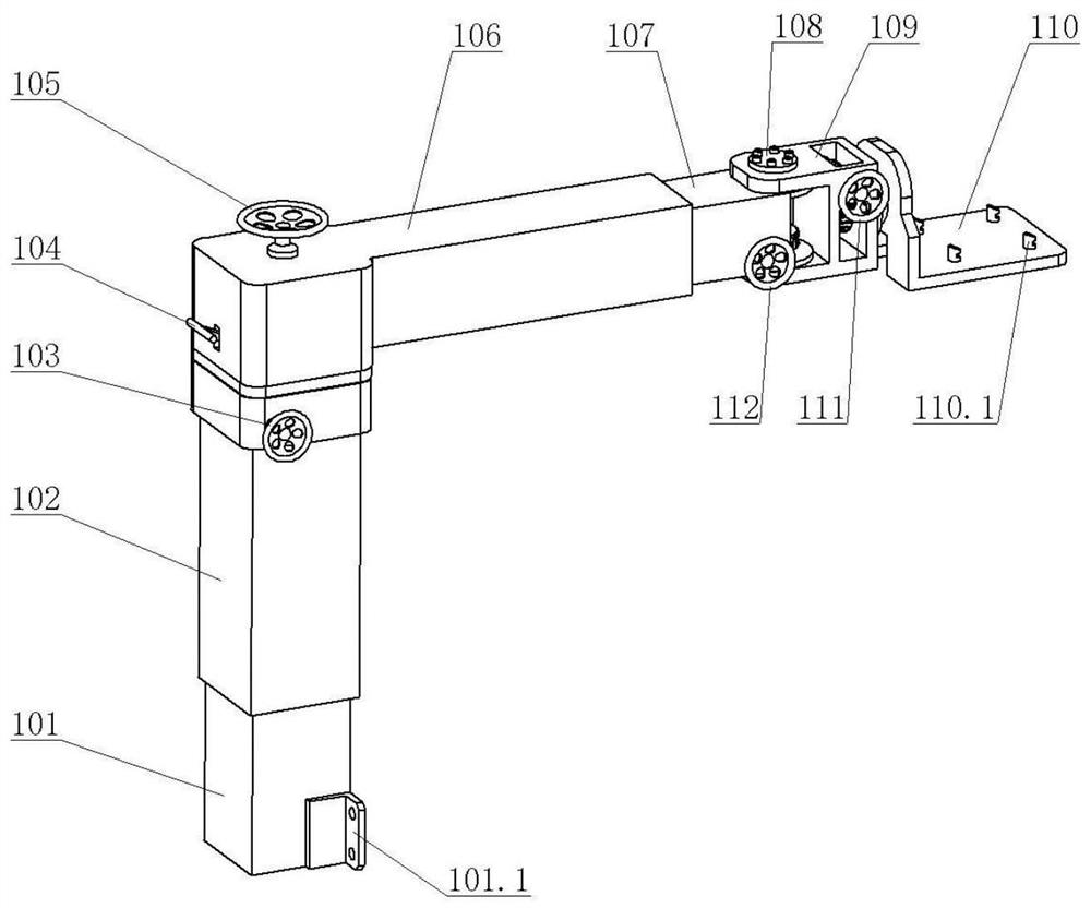
[0064] Such as figure 1 , figure 2 As shown, a medical instrument for patella fracture repair surgery, including a posture adjustment mechanism 1, a connecting mechanism 2, a double thread end tightening mechanism 3, and a single thread end tightening mechanism 4, is characterized in that: the posture adjustment mechanism 1 can be combined with The connection mechanism 2 realizes quick connection and release. The double thread end tightening mechanism 3, the single thread end tightening mechanism 4 and the connection mechanism 2 also adopt a modular connection structure, which can realize quick connection and release. The posture adjustment mechanism 1 is used To realize the position and posture adjustment of the...


PUM


Abstract

The invention discloses a medical instrument for patella fracture repair surgery. The medical instrument comprises a pose adjusting mechanism, a connecting mechanism, a double-thread-end tightening mechanism and a single-thread-end tightening mechanism. The pose adjusting mechanism can be quickly connected and disconnected with the double-thread-end tightening mechanism and the single-thread-end tightening mechanism through the connecting mechanism; namely, a modular connecting structure is adopted between the pose adjusting mechanism and the connecting mechanism; and the pose adjusting mechanism is used for achieving position and pose adjustment of the double-thread-end tightening mechanism and the single-thread-end tightening mechanism. The double-thread-end tightening mechanism, the single-thread-end tightening mechanism and the connecting mechanism also adopt a modular connecting structure; the double-thread-end tightening mechanism can tighten the steel wires led out of double thread ends and steel wires led out of two single thread ends; and the single-thread-end tightening mechanism can tighten a steel wire led out of one single thread end.

Description

technical field [0001] The invention relates to the technical field of medical instruments, in particular to a medical instrument for patella fracture repair operation. Background technique [0002] The patella is located in front of the knee joint and in front of the lower end of the femur. It is the largest sesamoid bone in the human body and is embedded in the quadriceps tendon. It is a triangular flat bone and participates in the formation of the knee joint. The main function of the patella is to protect the knee joint. It has the function of avoiding the friction of the quadriceps tendon on the cartilage surface of the femoral condyle. It transmits the strength of the quadriceps and participates in the function of forming the knee extensor device. It also maintains the stability of the knee joint in a half-squat position and prevents excessive adduction of the knee joint. The functions of abduction and extension and flexion, as well as the function of increasing the rot...

Claims


Application Information

Patent Timeline
Patent Type & Authority Applications(China)
IPC IPC(8): A61B17/82A61B17/88
CPCA61B17/82A61B17/8861
Inventor 不公告发明人
Owner 郜鹏
Learn More